Heated die for hot forming

a technology of heat treatment and dies, which is applied in the direction of manufacturing tools, cutting tools, shaping tools, etc., can solve the problems of cumbersome and expensive use of many separate powered and controlled heating cartridges, particularly in the design and operation of forming tools, and achieve simple power and control, reduce the cost of parts made, and increase the productivity of tools

Active Publication Date: 2007-01-09
GM GLOBAL TECH OPERATIONS LLC
View PDF7 Cites 23 Cited by
  • Summary
  • Abstract
  • Description
  • Claims
  • Application Information

AI Technical Summary

Benefits of technology

[0009]A preferred goal of the analysis is to position a plurality of heater cartridges within the body of the die so that desired forming surface temperatures can be maintained by sensing the temperature at a selected location within the body or surface for controlling the activation of the cartridges from a single power source. In its simplest and preferred embodiment, all heaters in the die are turned on or off at the same time using a single electronic controller. The electrical heating and control design economizes and simplifies operation of the forming process and the maintenance and replacement of heater elements. The material and dimensions of the die have been established by design. The physical properties of the material, including its thermal conductivity; assumed temperatures at the forming surface of the die and its exposed sides and press (bed or ram) attaching surface; and the dimensions of the die are among the parameters used in the analysis for location of the heaters.
[0012]This practice enables the construction of a massive, internally heated forming die with electrical resistance heaters that can be simply powered and controlled. And the temperature of the forming surface of the tool can be effectively controlled within a useful narrow working range in response to variations in temperature measured at a single location, or relatively few locations, in the die. Simplified and effective temperature control of the forming surface during repeated part forming cycles increases the productivity of the tool and reduces the cost of the parts made on it.

Problems solved by technology

The design and operation of forming tools is particularly challenging in the shaping of large parts at high temperatures.
However, the use of many separately powered and controlled heating cartridges has proven cumbersome and expensive.

Method used


Image

  • Heated die for hot forming
  • Heated die for hot forming
  • Heated die for hot forming

Examples


Embodiment Construction

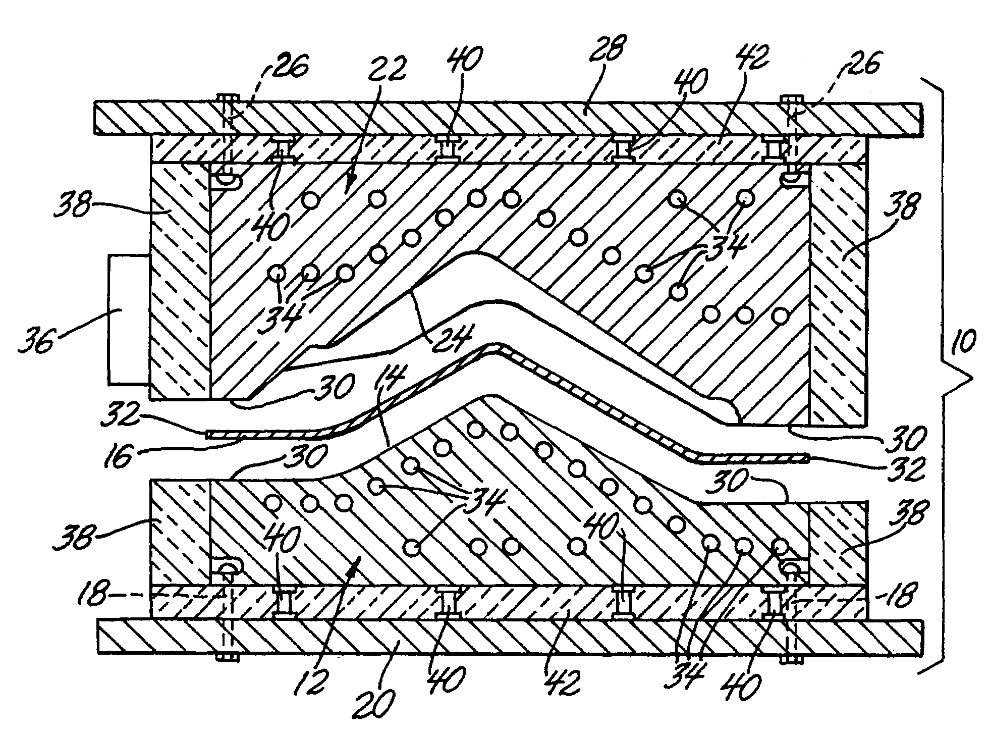
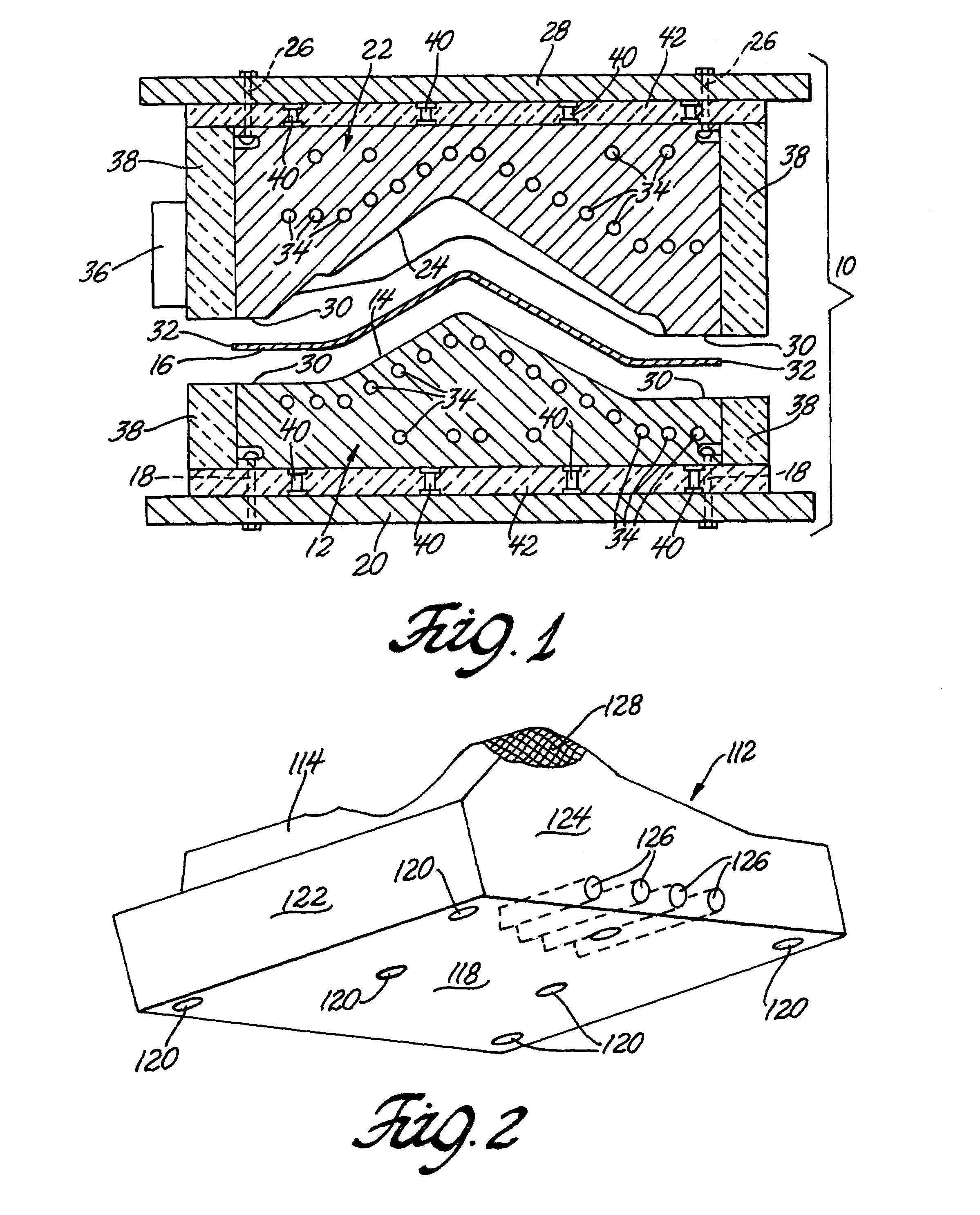
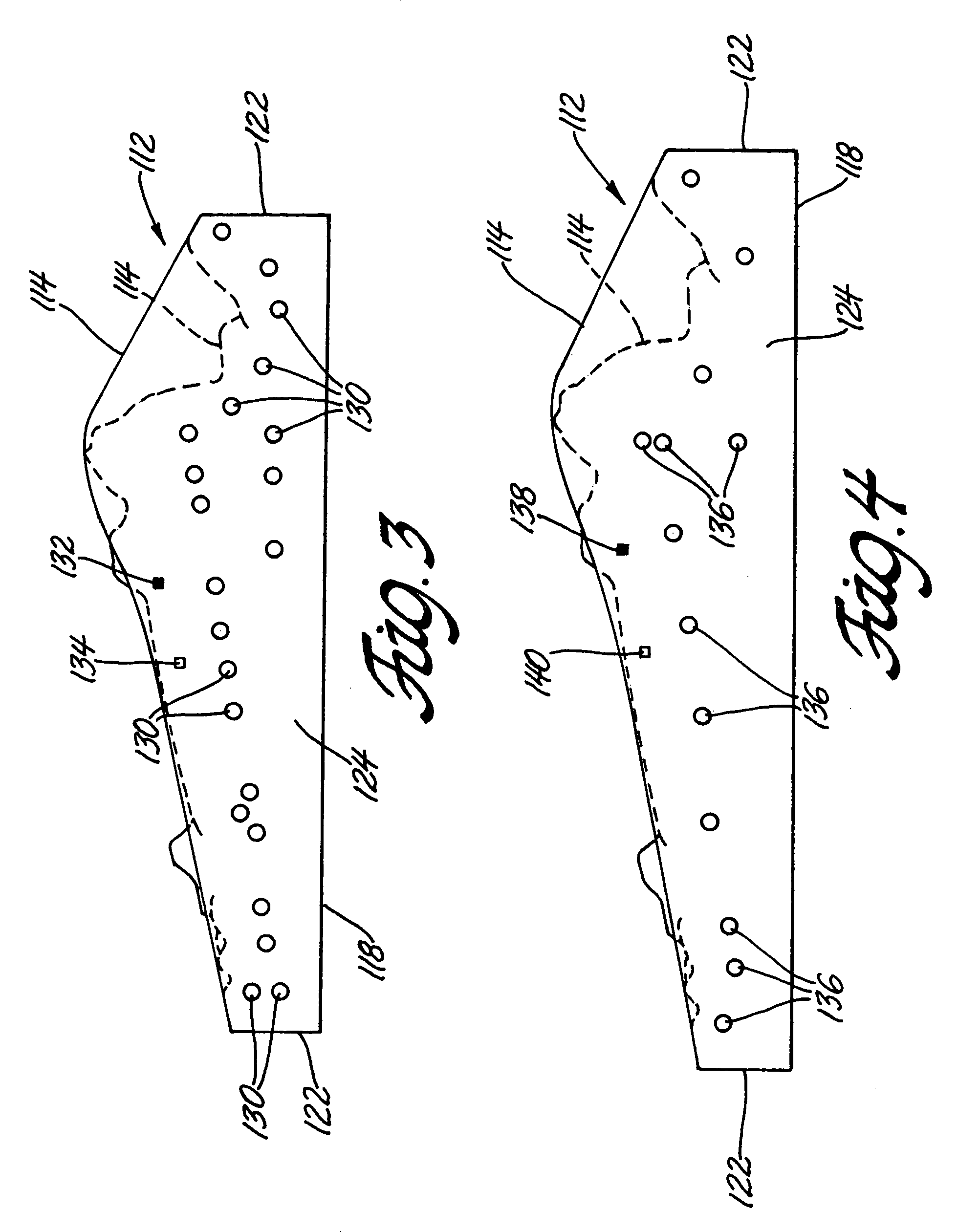
[0018]U.S. Pat. No. 6,253,588 to Rashid et al, and assigned to the assignee of this invention, describes Quick Plastic Forming of Aluminum Alloy Sheet Material. In Quick Plastic Forming (QPF), a blank of superplastic aluminum alloy is heated to the forming temperature and stretched by air pressure against a forming tool to make an aluminum body panel. QPF is a hot stretch forming process, or hot blow forming process like superplastic forming. However, QPF is practiced at a lower temperature and higher strain rates where deformation mechanisms of grain-boundary sliding and solute-drag creep both contribute to material deformation, and total elongations are somewhat less than those obtained for true superplastic behavior. This invention provides improved internally heated forming dies or tools for QPF and other hot forming or molding processes for materials.

[0019]Challenges in making internally heated forming dies for automotive body panels arise from the size of the panels (typically...


PUM

PropertyMeasurementUnit
temperaturesaaaaaaaaaa
sizeaaaaaaaaaa

Abstract

A hot forming tool is heated with multiple electrical resistance cartridge heaters. The heaters are located in the body of the tool so as to maintain the entire forming surface within a predetermined temperature range. Numerical thermal and optimization analyses direct the placement of the heaters so that when each heating element is simultaneously powered on for an identical fraction of the time, an acceptable temperature distribution will be produced within the tool at the tool operating temperature.

Description

TECHNICAL FIELD[0001]This invention pertains to heated metal dies or tools for hot forming or molding. More specifically, this invention pertains to such dies in which electrical resistance cartridge heaters are arranged within the tool such that when each heating element is powered on for an identical fraction of the heating time, an acceptable temperature distribution will be produced within the tool at the tool operating temperature.BACKGROUND OF THE INVENTION[0002]The design and operation of forming tools is particularly challenging in the shaping of large parts at high temperatures. For example, superplastic aluminum and titanium sheet alloys have been formed at temperatures of the order of 500° C. for aluminum and 1100° C. for titanium into one-piece panels or other articles of complex shape. In hot stretch forming, heated blanks of superplastic sheet material are gripped at their edges and placed over the forming surface of a heated tool. One side of the sheet is stretched in...

Claims


Application Information

Patent Timeline
Patent Type & Authority Patents(United States)
IPC IPC(8): B21D37/16B21D39/20
CPCB21D37/16Y10S72/709
Inventor SCHROTH, JAMES G.HAMMAR, RICHARD H.
Owner GM GLOBAL TECH OPERATIONS LLC
Why Eureka
Try Eureka