Light manifold for automotive light module

a technology for automotive light modules and manifolds, which is applied in the direction of semiconductor devices for light sources, lighting and heating apparatus, transportation and packaging, etc., can solve the problems that not all automotive applications, such as the stop function of tail lights, have been effectively produced, etc., and achieve the effect of facilitating the reproduction of automotive light functions

Inactive Publication Date: 2007-01-09
VARROC LIGHTING SYST SRO
View PDF135 Cites 125 Cited by
  • Summary
  • Abstract
  • Description
  • Claims
  • Application Information

AI Technical Summary

Benefits of technology

[0004]One embodiment of the present invention provides a light manifold for a light module which facilitates reproduction of automotive light functions. Generally, the light manifold distributes light from a light source and includes the main body of light transmitting material. The main body defines a longitudinal axis and a lateral axis. The main body has opposing first and second surfaces

Problems solved by technology

Unfortunately, not all automotive applications, such as the stop function of a tail light, have b

Method used


Image

  • Light manifold for automotive light module
  • Light manifold for automotive light module
  • Light manifold for automotive light module

Examples


Embodiment Construction

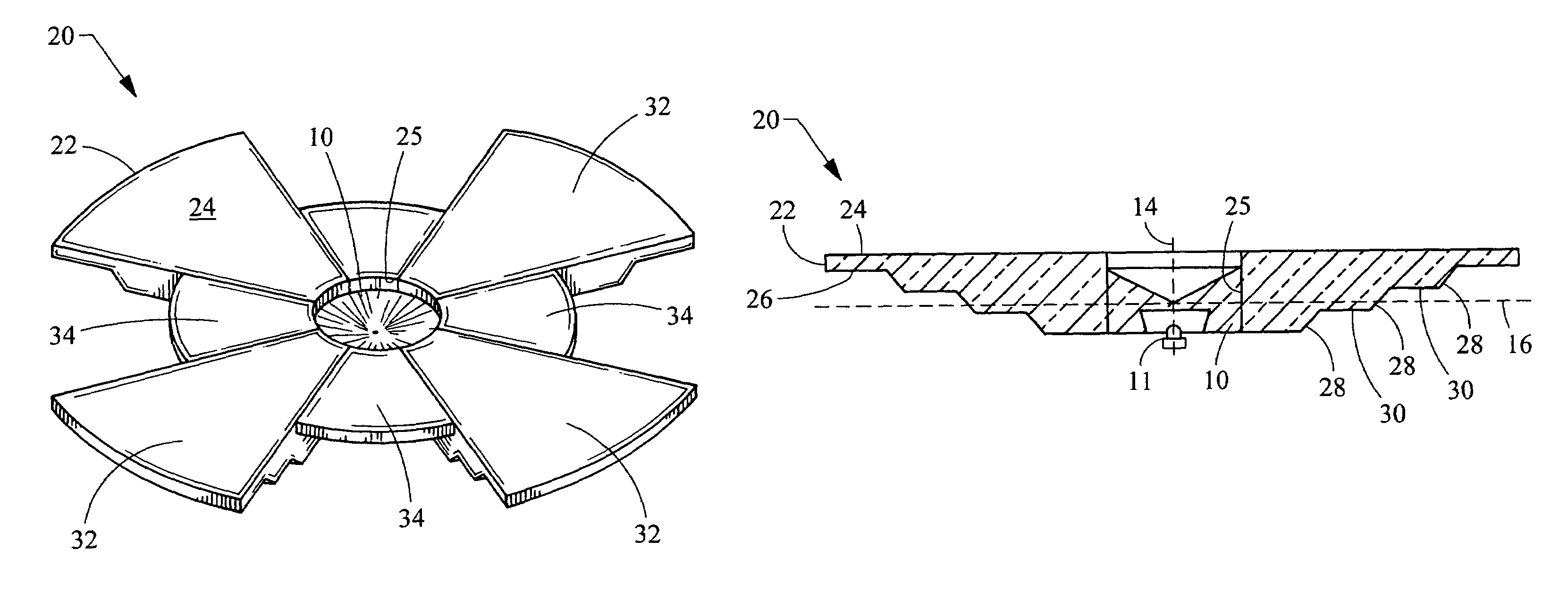
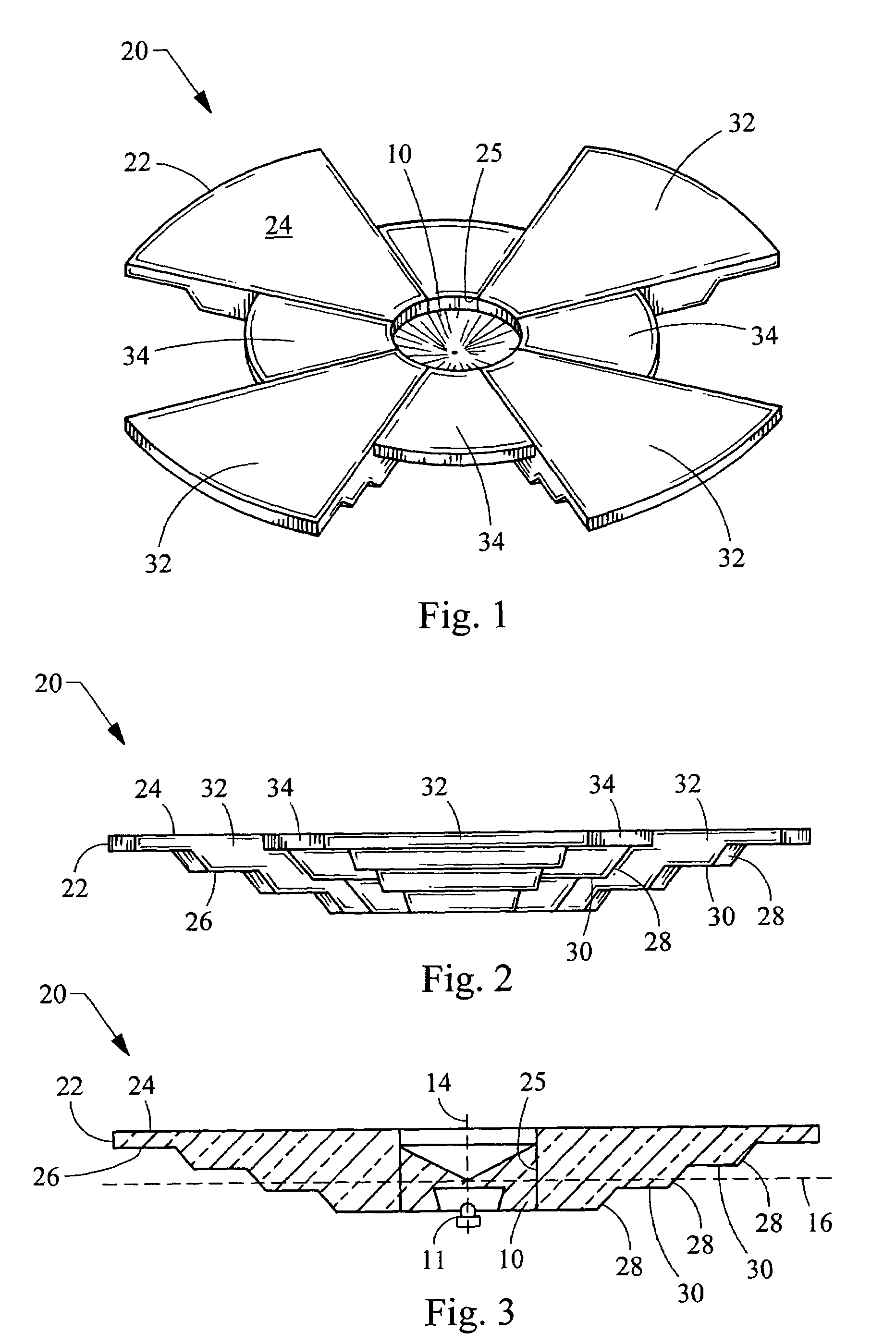
[0015]Turning now to the figures, FIGS. 1–3 depict a light manifold 20 for use with the light module having a near field lens 10 and light source 11. Generally, the light manifold includes a disc-shaped main body 22 constructed of a light transmitting material, and preferably a plastic such as acrylic although any light transmitting material may be employed. The main body 22 defines a longitudinal axis 14 along which light is directed, and a lateral axis 16 perpendicular to the longitudinal axis 14. As used herein, the lateral direction may also be referred to as the radial direction, and encompasses all directions which are generally transverse to the longitudinal axis 14. The main body includes a light emitting surface 24 and a light reflecting surface 26. The light reflecting surface 26 will be referred to herein as the first surface 26 and the light emitting surface 24 will be referred to as the second surface 24. The main body 22 also includes an inner laterally facing surface ...


PUM


Abstract

A light manifold for an automotive light module emitting light to the side of a longitudinal axis along which light is to be directed. The light module is structured in a manner that permits the creation of light distribution patterns for particular functions, such as the stop light function for an automobile, that are otherwise difficult to effectively produce.

Description

FIELD OF THE INVENTION[0001]The present invention relates generally to automotive light modules and light manifolds therefor, and more particularly relates to light manifolds for near field lenses collecting and directing light laterally relative to the light source.BACKGROUND OF THE INVENTION[0002]Light emitting diodes (LED's) are fast becoming a preferable light source for automotive lighting applications, as they consume less power but provide light output which is acceptable for such applications. In order to employ LED's for automotive applications, high levels of efficiency must be obtained in both light collection as well as light distribution. Typically, reflectors or lenses or light pipes are utilized to collect and distribute the light for the particular lighting application. Unfortunately, not all automotive applications, such as the stop function of a tail light, have been effectively produced utilizing an LED light source in such reflectors, lenses or light pipes.[0003]...

Claims


Application Information

Patent Timeline
IPC IPC(8): F21V9/00
CPCF21S48/215F21S48/2243F21S48/2262F21Y2101/02F21V5/04F21S43/14F21S43/239F21S43/243F21Y2115/10
Inventor CHINNIAH, JEYACHANDRABOSEFALLAHI, AMIR P.ERION, JEFFREY ALLENSAYERS, EDWIN MITCHELLJONES, THOMAS LEE
Owner VARROC LIGHTING SYST SRO
Why Eureka
Try Eureka