Flame simulating assembly

a technology of flame simulating and assembly, which is applied in the field of flame simulating assembly, can solve the problems of affecting the overall affecting the overall simulation effect of the flame simulating assembly,

Active Publication Date: 2007-01-16
GLEN DIMPLEX AMERICAS LTD
View PDF92 Cites 47 Cited by
  • Summary
  • Abstract
  • Description
  • Claims
  • Application Information

AI Technical Summary

Problems solved by technology

Among other things, electric flame simulating assemblies can be used in an interior room (such as in a condominium building or a hotel) from which access to a chimney (i.e., for an actual fireplace) would be difficult.
Due to this, the overall effect presented by these flame simulating assemblies is often not as realistic as may be desirable.
This is because the relatively smaller depth of the typical flame simulating assembly, as compared to the usual depth of a real fireplace, tends to undermine the overall simulation effect sought with the typical flame simulating assembly.

Method used


Image

  • Flame simulating assembly
  • Flame simulating assembly
  • Flame simulating assembly

Examples


embodiment 110

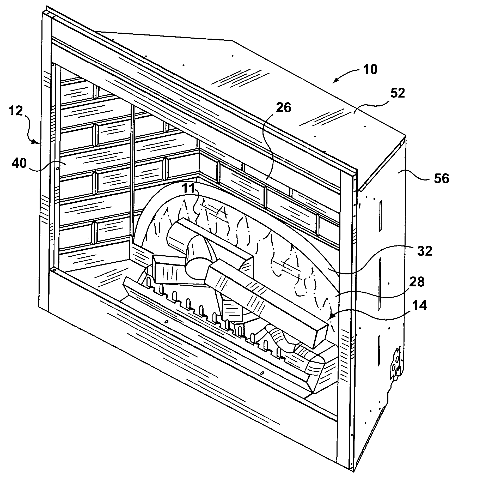
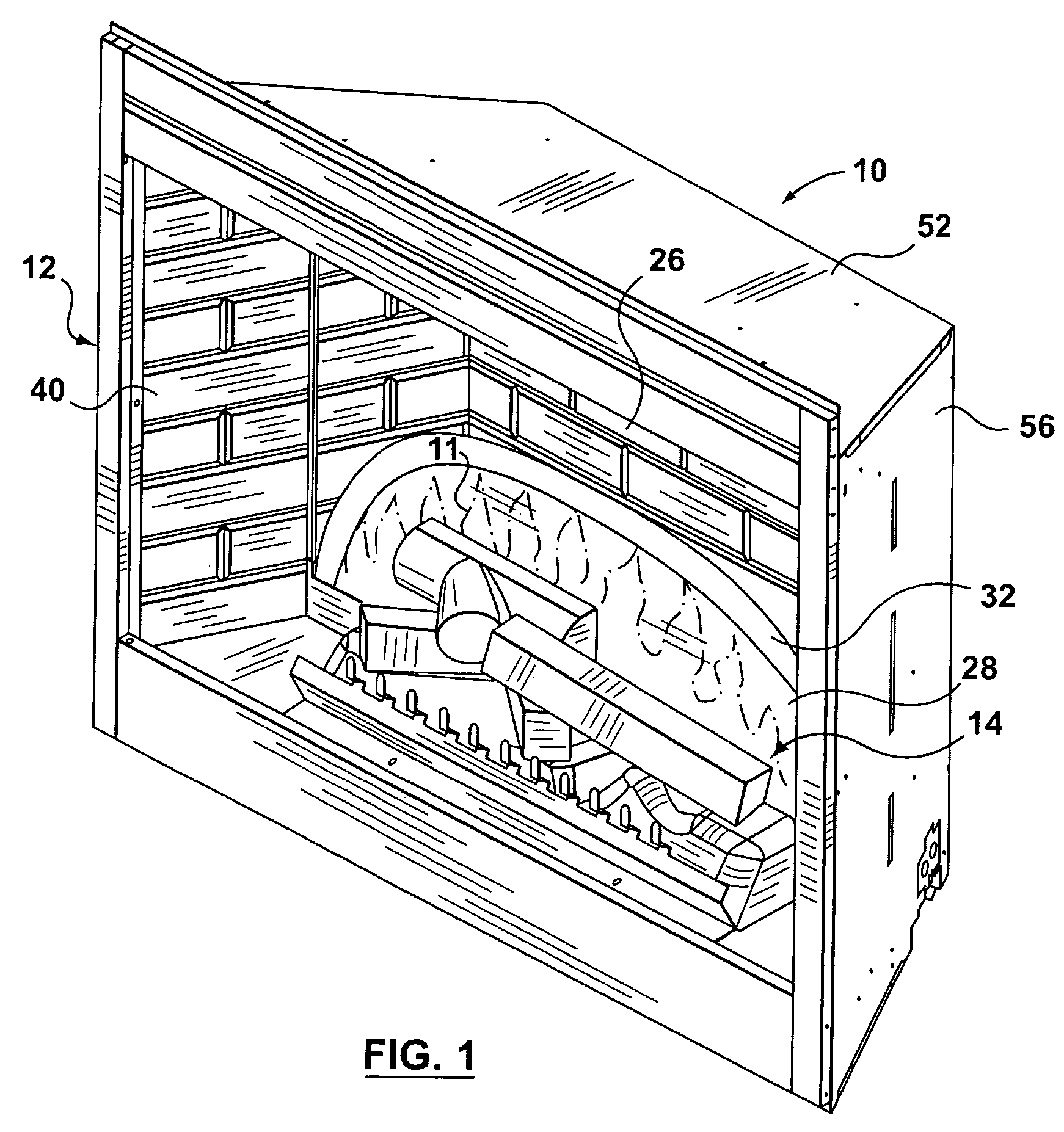
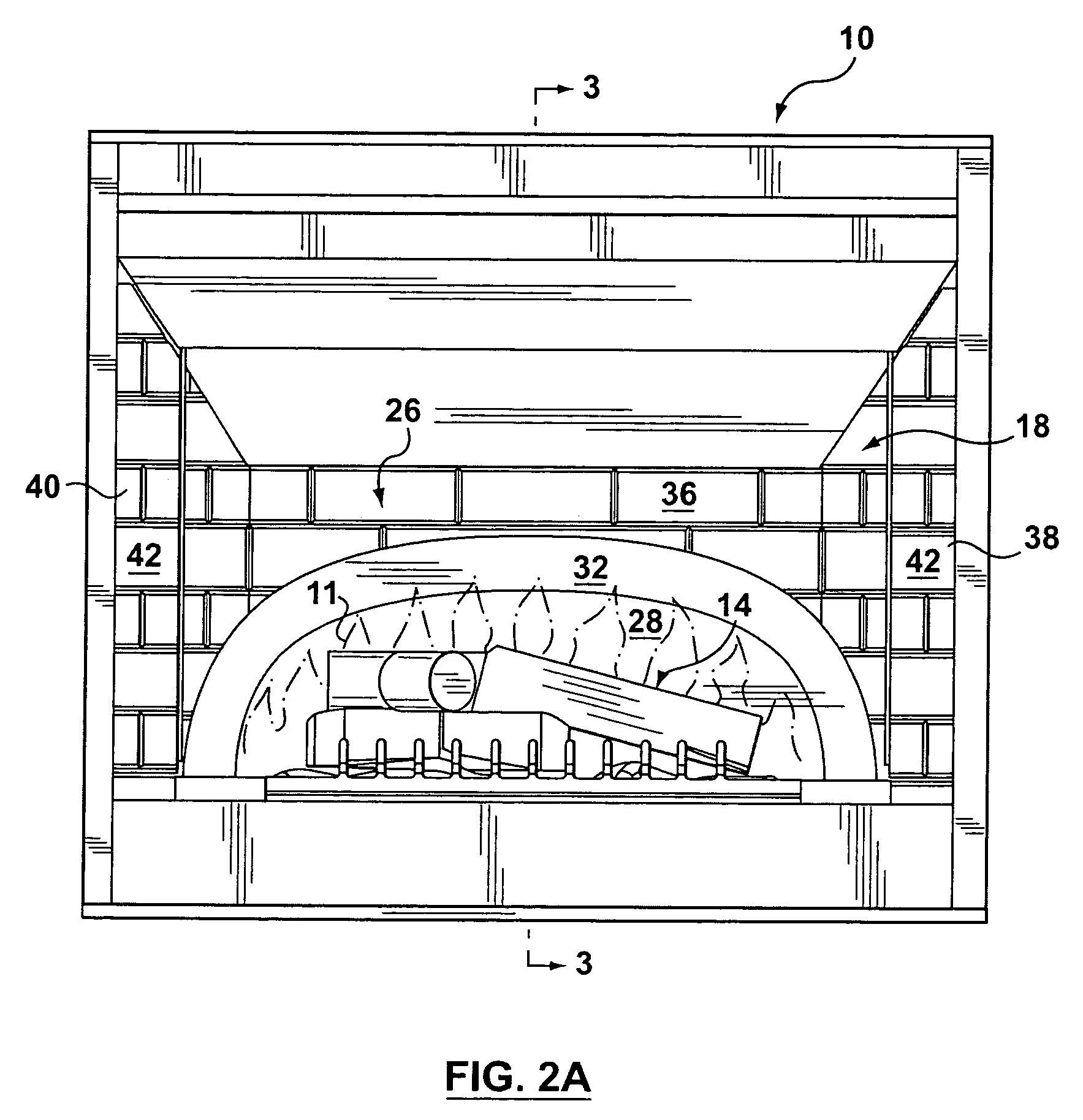
[0049]An alternative embodiment 110 of the flame simulating assembly is shown in FIGS. 4, 5 and 6A. The flame simulating assembly 110 does not include a simulated fuel bed, but is adapted for use with a simulated fuel bed (not shown) which is to be provided separately by a user (not shown). The simulated fuel bed, when provided, is to be located proximate to a front side 112 of the flame simulating assembly 110. The flame simulating assembly 110 includes a cavity 160, and also has a light source 116 for providing an image of flames 11 and the screen 18 positioned in the cavity 160. The flame simulating assembly 110 also includes the simulated interior fireplace wall 26 positioned behind the screen 18. The screen 18 includes the front surface 20 with the viewing region 28, the observation region 30, and the transition region 32 positioned between the viewing region 28 and the observation region 30. The viewing region 28 is positioned, at least in part, at the bottom of the screen 18—...

embodiment 318

[0060]An alternative embodiment 318 of a screen is shown in FIGS. 12–14. As can be seen in FIG. 12, the screen 318 is included in an alternative embodiment of a flame simulating assembly 310. The flame simulating assembly 330 includes the housing 48, which includes the back wall 50, a top wall 352, a bottom wall 54, and at least two side walls 56, 58 extending between the top and bottom walls 352, 54. The flame simulating assembly 310 also includes a simulated interior fireplace wall 326 mounted on or positioned proximal to the back wall 50. The screen 318 is positioned behind the simulated fuel bed 14 and in front of the simulated interior fireplace wall 326.

[0061]As can be seen in FIG. 12, the flame simulating assembly 310 also includes a light source 316, a flicker element 344 positioned in a path of light 319 (schematically represented by arrows 315, 317), and a flame effect element 346, also positioned in the path of light 319. The flame effect element 346 is for configuring li...


PUM


Abstract

A flame simulating assembly for providing an image of flames. The flame simulating assembly has a light source for producing the image of flames, a screen, and a simulated interior fireplace wall positioned behind the screen. The screen has a front surface and is positioned in a path of light from the light source. The screen is adapted to transmit the image of flames through the front surface. The front surface of the screen includes an observation region, which is adapted to permit observation of part of the simulated interior fireplace wall.

Description

FIELD OF THE INVENTION[0001]The present invention relates to a flame simulating assembly adapted for displaying an image of flames.BACKGROUND OF THE INVENTION[0002]Various types of flame simulating assemblies are known. Often, a flame simulating assembly is designed to be included in an electric fireplace, to simulate a fire in a real fireplace. For example, U.S. Pat. No. 4,965,707 (Butterfield) discloses a simulated flame system for an electric fireplace in which a light source is combined with billowing ribbons to simulate flames. The effect resulting tends to resemble flames from a coal fuel source more than flames from a wood fuel source. The flames for burning wooden logs tend to be more active and extend higher above the fuel source.[0003]Known flame simulating assemblies have certain advantages over actual fireplaces, in which a combustible fuel (usually wood or coal, or natural gas) can be burned. Among other things, electric flame simulating assemblies can be used in an int...

Claims


Application Information

Patent Timeline
Patent Type & Authority Patents(United States)
IPC IPC(8): G09F19/00F24C7/00
CPCF24C7/004
Inventor HESS, KRISTOFFERSTINSON, KELLY
Owner GLEN DIMPLEX AMERICAS LTD
Why Eureka
Try Eureka