Electric fireplace

a technology of electric fireplaces and fireplaces, applied in the field of electric fireplaces, can solve the problems of significant servicing difficulties and the inability to permanently mount fireplaces in building walls, and achieve the effect of convenient replacement, convenient removal and replacemen

Active Publication Date: 2008-01-17
TWIN STAR INT
View PDF65 Cites 34 Cited by
  • Summary
  • Abstract
  • Description
  • Claims
  • Application Information

AI Technical Summary

Benefits of technology

[0004] The invention is based on the development of an electric fireplace which is constructed so that operational components can be easily removed and replaced from the front rather than from the rear for convenient servicing and replacement, and permitting the fireplace to be permanently built into a building wall.

Problems solved by technology

As a result, such fireplaces cannot be mounted permanently in a building wall without creating significant servicing difficulties.

Method used


Image

  • Electric fireplace
  • Electric fireplace
  • Electric fireplace

Examples


Embodiment Construction

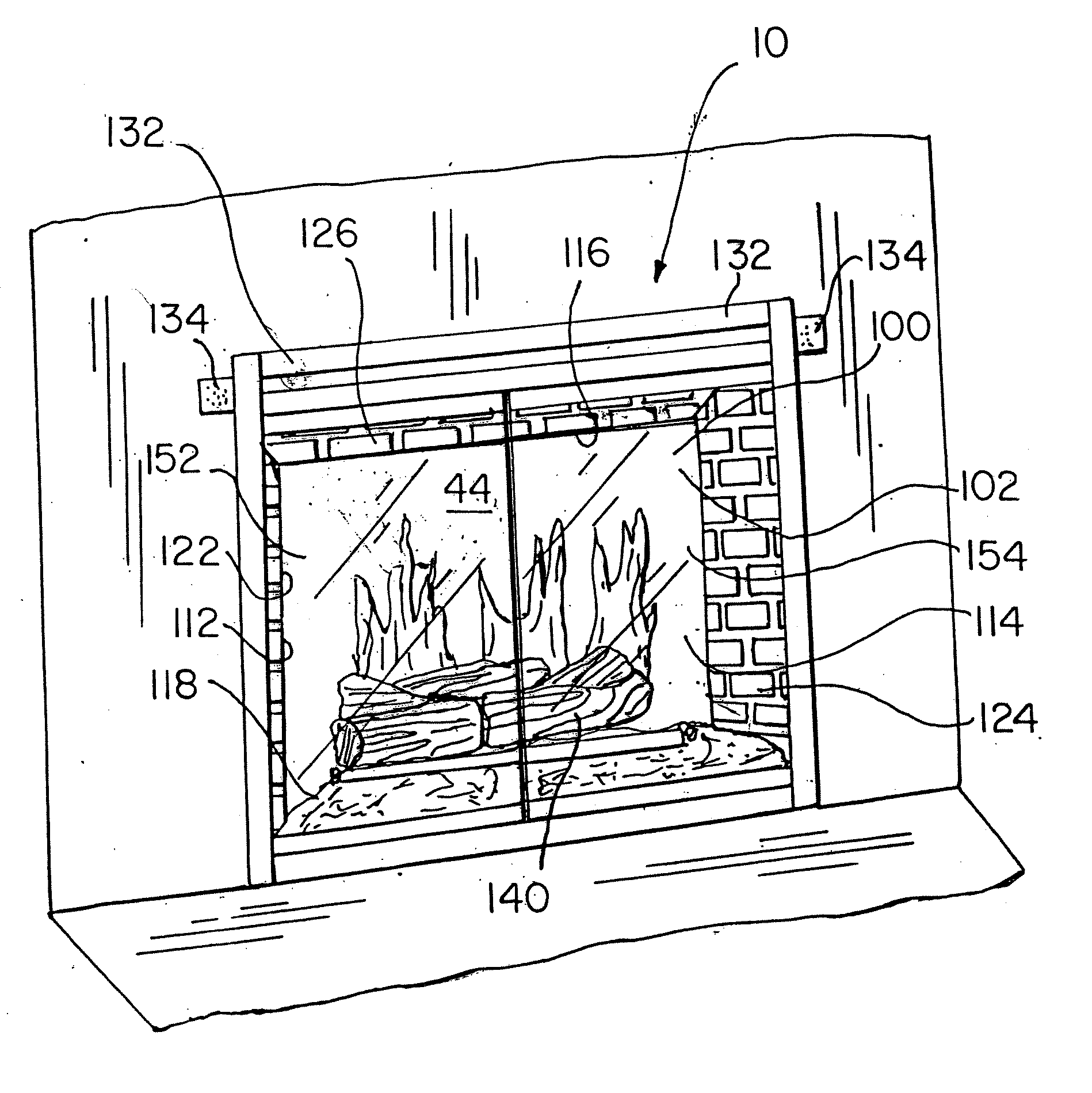
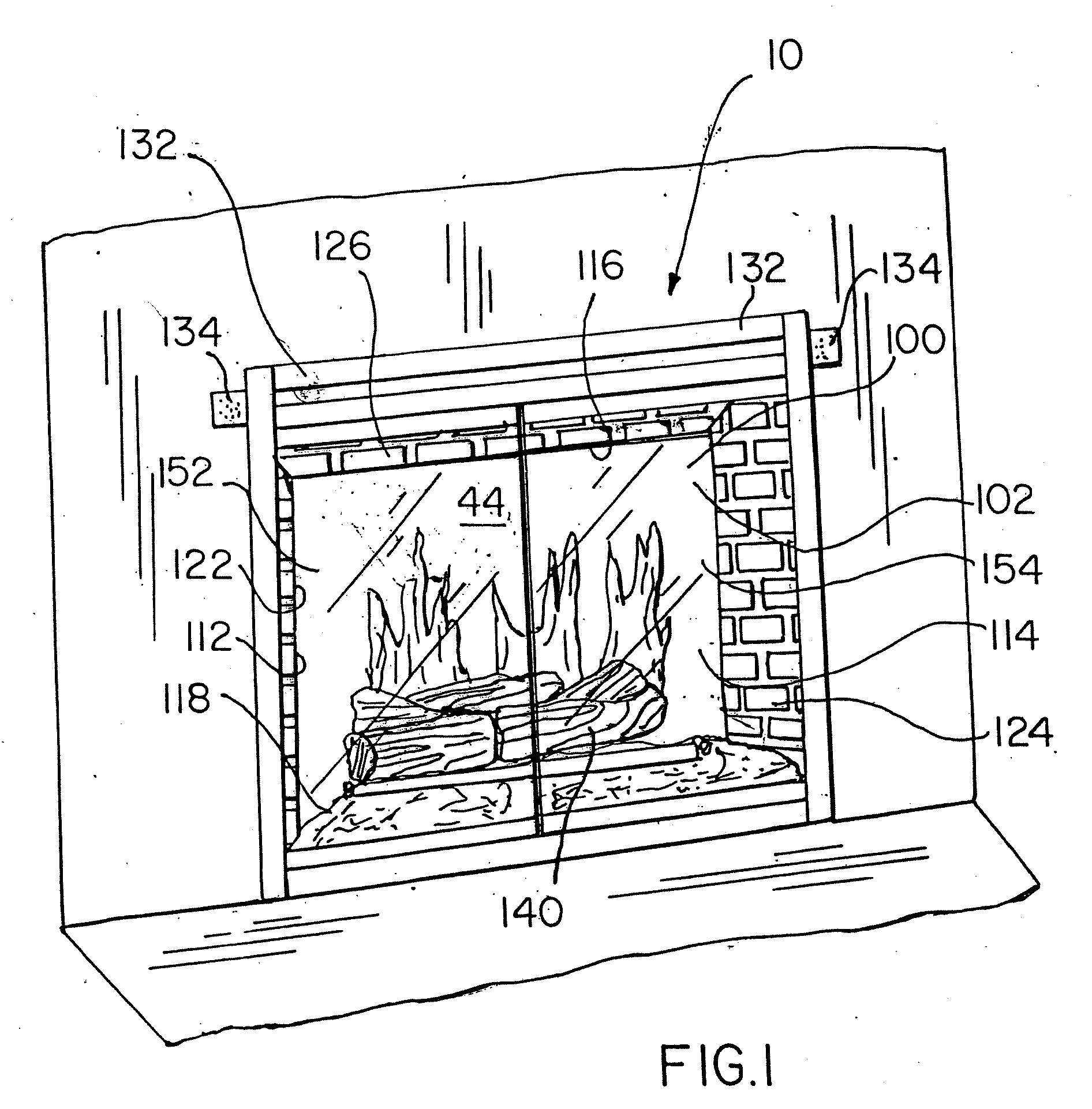
[0026] Referring to FIGS. 1-12, an exemplary embodiment of an electric fireplace 10 includes a metal fireplace housing 100 having a housing open end 102, housing first and second side walls 112 and 114, a housing top wall 116, a housing floor 118 and a housing back wall 120. In FIG. 1, the metal fireplace housing 100 is shown permanently mounted within a recess in a building wall. A removable flame simulator 20 and a removable hot air generator 60 are both mounted inside the housing 100 and are framed by removably fastened cosmetic panels 122, 124, 126. The cosmetic panels have a brick finish and include first and second side panels 122 and 124 and a brick top panel 126 and preferably are fastened to the housing 100 and to these structures with magnetic fasteners 128 for removal without tools.

[0027] An ember bed 140 is removably fastened to the housing floor 118 in front of the flame simulator 20, and can be removed to gain access to the flame simulator 20. The ember bed 140 can ta...


PUM

PropertyMeasurementUnit
average sizeaaaaaaaaaa
structureaaaaaaaaaa
shapesaaaaaaaaaa

Abstract

An electric fireplace includes a fireplace housing having a housing first and second side walls and a housing top wall, a housing floor, a housing back wall, and a housing open end opposite the housing back wall; a flame simulator mounted inside the housing; a diffusion screen removably mounted upright within the housing in front of the flame simulator; an ember bed simulating the appearance of fireplace fuel such as fire wood, embers or coal, and removably mounted inside the housing in front of the flame simulator, so that removal of the ember bed and the flame cutout panel provides access to the flame simulator from the housing open end; and a hot air generator removably mounted inside the housing to be accessible from the housing open end.

Description

CROSS-REFERENCE TO RELATED APPLICATIONS [0001] The present application claims the priority of U.S. provisional application No. 60 / 797,815 filed on May 5, 2006.FIELD OF THE INVENTION [0002] The present invention relates generally to the field of electric fireplaces. More specifically the present invention relates to an electric fireplace constructed so that operational components can be easily accessed, removed or replaced from the front of the fireplace rather than from the rear for convenient servicing and replacement, and permitting the fireplace to be permanently built into a building wall. BACKGROUND [0003] Electric fireplaces having the structural appearance of a conventional fireplace and containing mechanisms for simulating the appearance of a fire and producing heat electrically have been gaining popularity over the last several years. Conventionally, electric fireplaces are constructed so that operational components such as flame simulators and hot air generators can be ser...

Claims


Application Information

Patent Timeline
Patent Type & Authority Applications(United States)
IPC IPC(8): F24C7/06
CPCF24C7/004
Inventor BOURNE, WILLIAM SCOTT
Owner TWIN STAR INT
Why Eureka
Try Eureka