Portable gas powered fluid dispenser

a technology of fluid dispensers and gas-powered devices, which is applied in the direction of liquid/fluent solid measurement, container, volume measurement, etc., can solve the problems of spoiling the quality of caulking beads being dispensed from the tubes, and achieve the effects of preventing excess material, minimizing unwanted deposits of viscous material, and spoiling the quality of caulking beads

Inactive Publication Date: 2007-01-16
LAFOND LUC MARCEL
View PDF104 Cites 52 Cited by
  • Summary
  • Abstract
  • Description
  • Claims
  • Application Information

AI Technical Summary

Benefits of technology

[0009]In one aspect, the invention is a hand held dispensing device defining a sealable chamber capable of preventing escape of pressurized operating fluids, including air or CO2, water, or other fluids used to power the device. (For ease of reference, the terms “sealable chamber” and “sealable housing” include chambers and housings designed to inhibit unintended escape of various pressurized gases and other fluids.) The chamber is made to receive containers that are typically manufactured and supplied separately, apart from the dispensing device. The device receives these later acquired containers within the chamber. In some instances, the chamber may be varied (for example, by replacing an existing modular housing with another housing of different size and shape) to receive a different type or size of container. In some instances, the container may be a rigid tube defining a hollow sleeve. Typically, the rigid tube comes with a plunger loaded within the hollow sleeve, to expel the viscous material from the tube, when the plunger is subjected to load. In this case, the rigid tube and the plunger are loaded into the chamber together, and after use, the tube and the included plunger are removed from the chamber. It is preferred that pressurized fluids introduced into the chamber during operation (for example, compressed gas) will surround the sleeve and an exposed surface of the plunger so that there will be an equalization of pressure around the tube, to maintain a tight seal between the sleeve and the plunger positioned within the sleeve. In many instances, this feature will discourage the sleeve of the tube from ballooning outwardly to fill any gaps that may exist between the sleeve of the tube and the interior walls of the chamber. The equalizing pressurized gas surrounding the sleeve inhibits ballooning of the sleeve and possible movement of the inner wall of the sleeve away from the internal plunger. (By way of comparison, in earlier caulking gun designs, there is a tendency for such ballooning to occur, thus allowing pressurized gas to blow by the plunger of a caulking tube, bubble through the viscous fluid, and spoil the quality of the caulking bead being dispensed from the tube.)
[0010]In other instances, the chamber will be loaded with a container for viscous material that is a collapsible tube made with relatively thin, outer walls which may be folded as or when the container is emptied. Because the walls of these sausage type containers are still relatively flexible even when the container is filled, the containers will tend to fill the interior space of the chamber in the housing. Consequently, in many instances, the present device may be provided with a standard housing suitable for receiving the most common sizes of rigid tubes and sausage type containers. Where a collapsible tube is used, it is preferable to load a plunger piece into the chamber so that the plunger will press against one end of the sausage, to urge the viscous fluid to flow to a nozzle assembly. It is preferred that the plunger will form an air tight seal between itself and the interior wall of the surrounding chamber. An air tight seal should be provided to inhibit compressed gases or other pressurized fluids from by-passing the plunger, and interfering with the efficient expulsion of viscous material from the collapsible container. It is preferred that the compressed gases or other pressurized fluids will preferentially act upon an exposed surface of the plunger (and a corresponding end wall of the collapsible container), without imparting any significant pressure on other surfaces of the compressible container. If the plunger is not tightly sealed for sliding movement within the chamber, there may be a tendency for compressed fluids (for example, compressed gas) to by pass the plunger and flexible container and blow out of the nozzle, or create bubbles in the viscous material expelled from the dispensing device. It is also preferred that the plunger define a recess for gathering a folded portion of a collapsible container, as viscous material is expelled from that portion of the container. Preferably, the plunger piece may be removed from the chamber after use. A funnel may also be provided to fit over the other end of the collapsible container, to channel viscous material being expelled from the container, toward the nozzle assembly. A funnel may be used to minimize unwanted deposits of viscous material within the housing. After use of the collapsible container, the spent container and the funnel may be simultaneously withdrawn to prevent excess material from dirtying the interior of the housing. In other instances, it may be desirable to leave the funnel in place within the housing, if the operator expects to load the chamber with another container, or if the funnel is clean enough for later use.
[0027]The dispensing device of the present invention may provide one or more of the following advantages or other advantages which will become apparent upon a review of the present specification. By way of an example, one or more of the following advantages may be obtained:

Problems solved by technology

(By way of comparison, in earlier caulking gun designs, there is a tendency for such ballooning to occur, thus allowing pressurized gas to blow by the plunger of a caulking tube, bubble through the viscous fluid, and spoil the quality of the caulking bead being dispensed from the tube.)
If the plunger is not tightly sealed for sliding movement within the chamber, there may be a tendency for compressed fluids (for example, compressed gas) to by pass the plunger and flexible container and blow out of the nozzle, or create bubbles in the viscous material expelled from the dispensing device.

Method used


Image

  • Portable gas powered fluid dispenser
  • Portable gas powered fluid dispenser
  • Portable gas powered fluid dispenser

Examples


Embodiment Construction

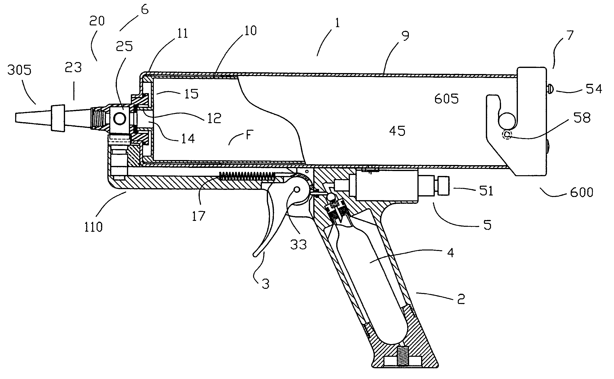
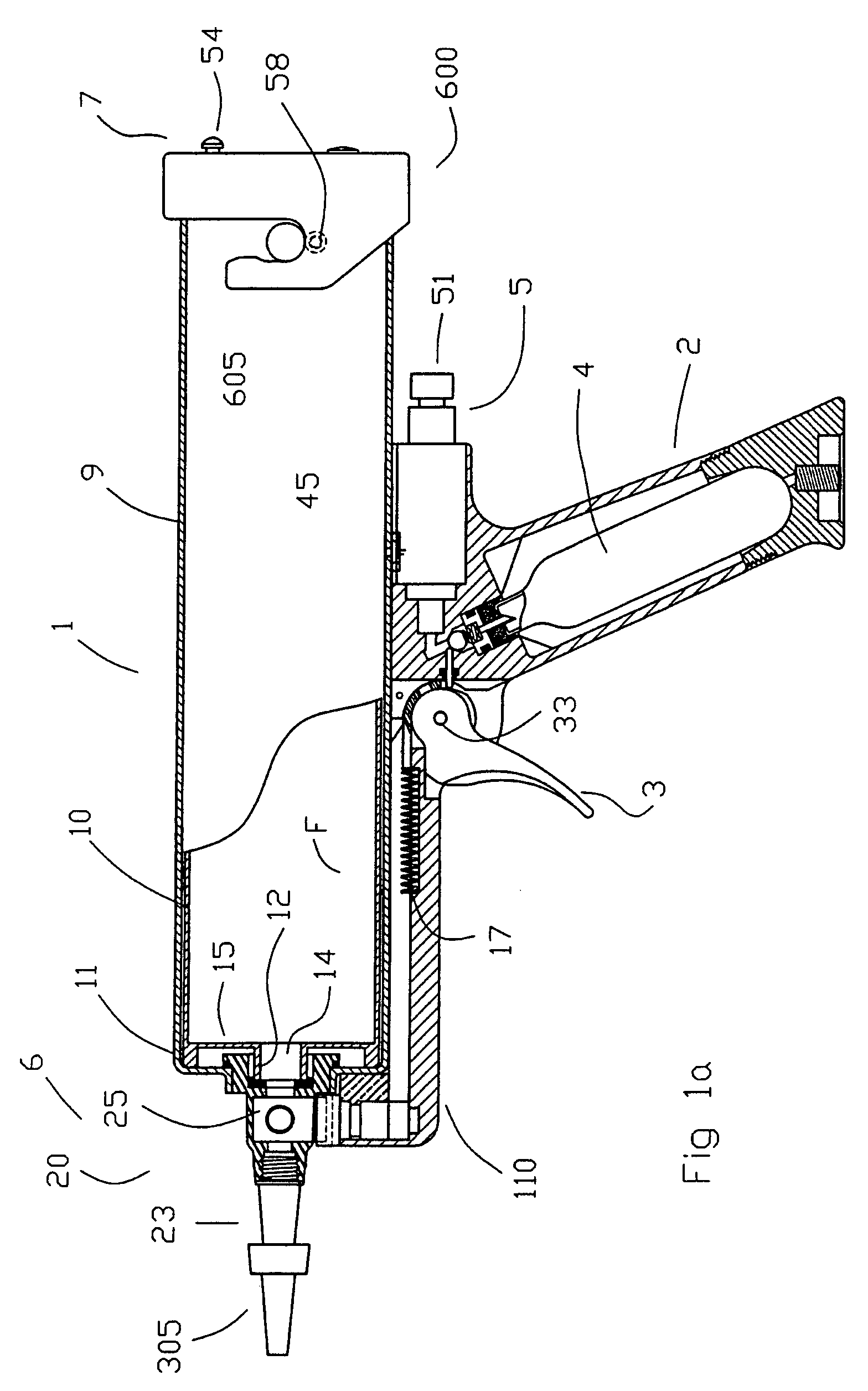
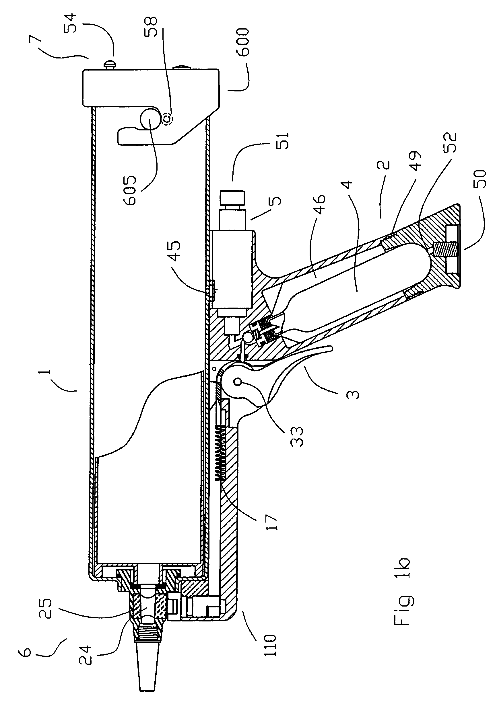
[0074]With reference to FIGS. 1A, 1B, 2A and 2B, a dispensing device 1 is shown with an air tight housing 9. The air tight housing 9 contains a tube 10 for storing a viscous, flowable material F, such as for example, caulking, sealant, mastic, or adhesive. The dispensing device 1 is provided with a handle grip 2 positioned below the housing, intermediate the dispensing end 6 and loading end 7. A control trigger 3 (used to activate the dispensing nozzle assembly 20 and permit pressurized gas to act on the material F) is pivotally mounted on the handle 2. Trigger 3 is operatively connected (by attachment at guide pin 30) to a flexible, but non-compressible, guide strap 31. The guide strap 31 is part of a guide 21 which operatively connects the movable trigger 3 to the rotatable spindle 25, at the spindle driver 28. Guide 21 is operatively connected to a rotatable guide mount 22 so that the guide mount 22 will rotate upon sliding movement of the guide 21. Guide retainer 62 is positione...


PUM


Abstract

A caulking gun has a tubular chamber to surround sleeve-like rigid tubes and compressible sausage type containers containing viscous materials including sealants, adhesives, caulking, mastics and the like. When rigid tubes are loaded into the chamber, compressed gas is allowed to surround the sleeve and a plunger loaded within the rigid tube to equalize pressure around the outside of the rigid tube. If a sausage type container is loaded into the chamber, a removable plunger is also provided to form a tight seal between the perimeter of the plunger and the inner surface of the chamber. Compressed gas introduced into the chamber preferentially acts on the plunger and an underlying end wall of the sausage to expel the material, without imparting any significant pressure to other parts of the sausage. The caulking gun includes a variable flow rate nozzle which may be removed from the device. The nozzle may be replaced with similar or different nozzle pieces of various shapes and sizes, if desired. Hand operated controls vary the flow rate through the nozzle and control introduction of compressed gas when in use. These features may be incorporated into other portable, hand held dispensing devices powered by other pressurized fluids.

Description

CROSS-REFERENCE TO RELATED APPLICATIONS[0001]This application claims the benefit of U.S. provisional patent application Nos. 60 / 419,114, filed Oct. 18, 2002 entitled “Caulking Gun Powered by Pressurized Fluid” and 60 / 451,281, filed Mar. 4, 2003 entitled “Nozzle for Dispensable Viscous Materials” respectively.FIELD OF THE INVENTION[0002]The following invention relates to portable, powered fluid dispensers, including caulking guns and other devices for dispensing viscous materials, including sealants, lubricants, pastes, epoxies, and other viscous materials. The present invention includes caulking guns, grease guns and other dispensers for viscous materials. The dispensing devices of the present invention will have application in various residential, commercial, construction and industrial applications in which viscous materials will be dispensed.BACKGROUND[0003]Dispensable, viscous materials such as adhesives, epoxies, sealants, including caulking, pastes, lubricants, and other visco...

Claims


Application Information

Patent Timeline
Patent Type & Authority Patents(United States)
IPC IPC(8): B67D5/40B67D7/58B05C17/005B05C17/015
CPCB05C17/00503B05C17/00553B05C17/015B05C17/00559B05C17/0146B05C17/00596
Inventor LAFOND, LUC MARCEL
Owner LAFOND LUC MARCEL
Why Eureka
Try Eureka