Solenoid valve for fluid flow

a solenoid valve and fluid flow technology, applied in the direction of valve details, valve arrangement, valve operating means/releasing devices, etc., can solve the problems of increasing the cost and assembly time of the valve, and the valve design is not capable of enduring the many cycles of the valve opening and closing, so as to prolong the operation life of the valve and reduce the impact between the valve element and the valve sea

Active Publication Date: 2007-01-16
COPELAND COMFORT CONTROL LP
View PDF12 Cites 19 Cited by
  • Summary
  • Abstract
  • Description
  • Claims
  • Application Information

AI Technical Summary

Benefits of technology

[0004]In this preferred embodiment, the first spring biases the valve member against the stop, and the second spring biases the valve element against the valve seat. The solenoid moves the valve member away from the stop, which moves the valve element away from the seat. When the solenoid is de-energized, the valve member moves back to the stop under the bias of the first spring, and the valve element moves back toward the valve seat. The valve element contacts the valve seat first and continued movement of the valve member is accommodated by the second spring, until the stop engages the valve member, preventing the full impact of the valve member from being transferred to the valve element. Thus, in the preferred embodiment, the impacts between the valve element and the valve seat are reduced, which can extend the operational life of the valve.

Problems solved by technology

However, such valve designs are not capable of withstanding numerous cycles of the valve opening and closing due to the impact force imparted by the moveable member on the valve and valve seat.
Also, the typical valve design is such that a connection of both the inlet and outlet are required, which adds to the cost and assembly time of the valve.

Method used


Image

  • Solenoid valve for fluid flow
  • Solenoid valve for fluid flow
  • Solenoid valve for fluid flow

Examples


Embodiment Construction

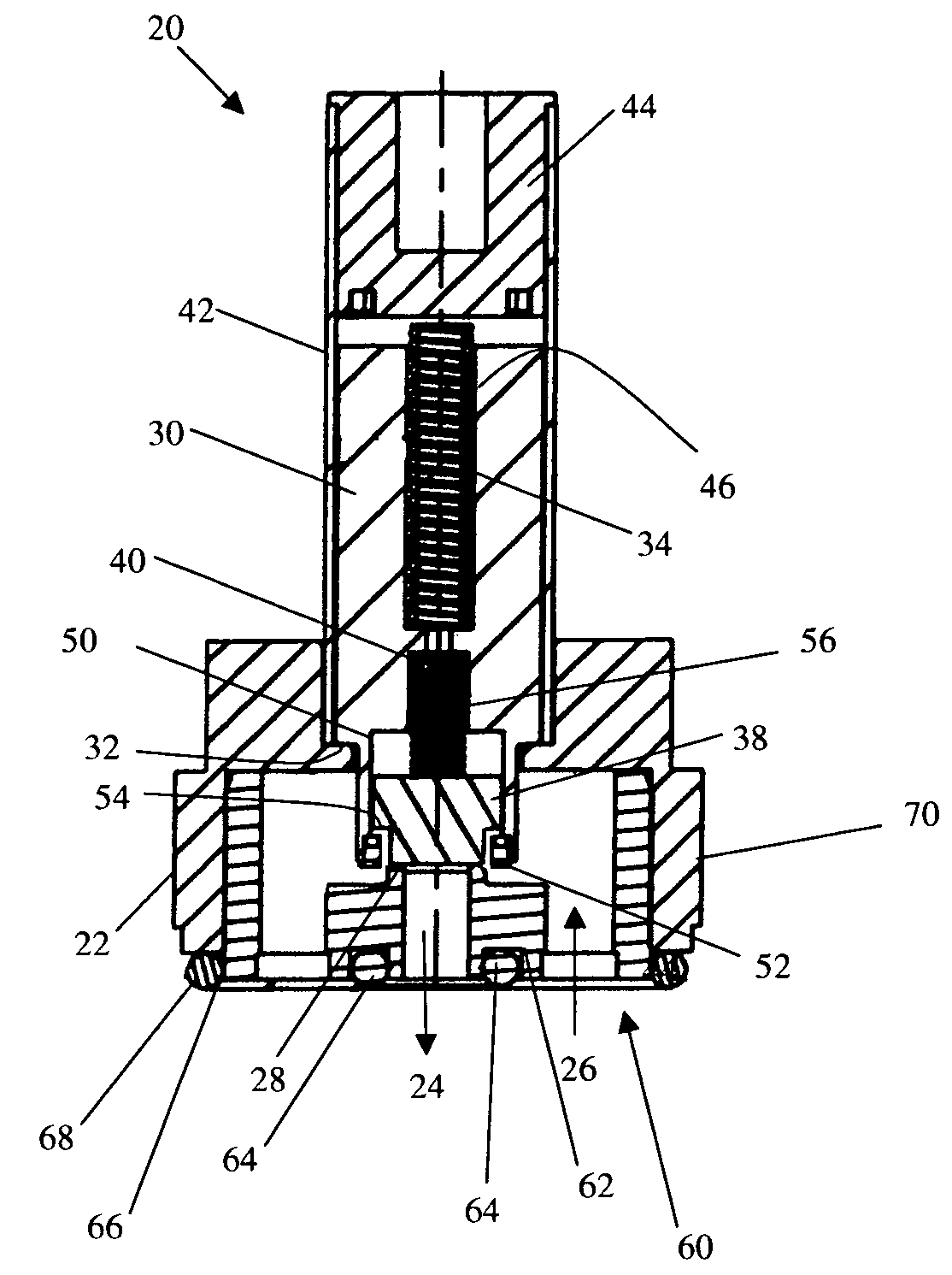
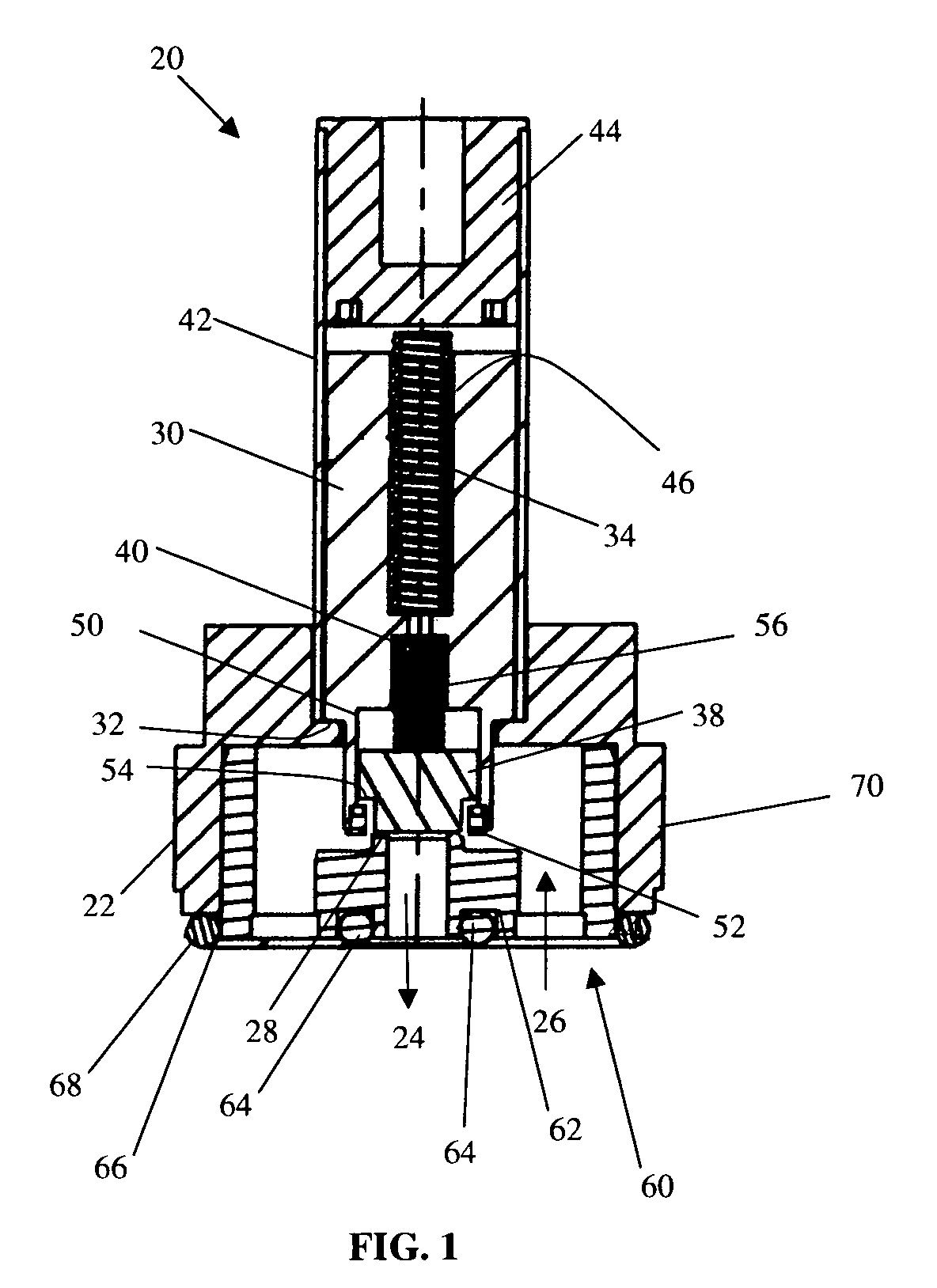
[0009]A solenoid valve in accordance with the principles of the present invention is indicated generally as 20 in FIG. 1. The solenoid valve 20 comprises a valve casing or housing 22 having at least one inlet 26 and at least one outlet. In the preferred embodiment there is a single outlet 24, and a plurality of inlets 26 concentrically positioned around the outlet 24. A valve seat 28 is positioned in the flow path between the inlet, 26 and the outlet 24.

[0010]A valve member 30 is mounted to move toward and away from the valve seat 28. The valve includes a stop 32 for engaging the valve member 30, and a spring 34 for biasing the valve member 30 toward the stop 32 and valve seat 28. In this preferred embodiment, the spring 34 is a coil spring, but the spring 34 could be any other element for applying a resilient force to the valve member 30, biasing it toward the stop 32.

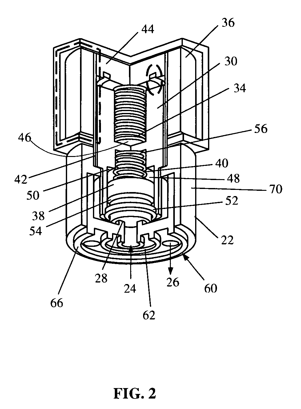
[0011]A solenoid 36 (FIG. 2), surrounds the valve member 30, and when energized moves the valve member 30 against t...


PUM


Abstract

A solenoid valve is provided that comprises a valve body having an inlet and an outlet, and a movable member for moving a valve element away from a valve seat to open the valve. The moveable member engages and moves the valve element away from the seat to an open position when the solenoid is actuated. When the solenoid is not actuated, a biasing spring moves the moveable member to disengage from the valve element, which returns to a closed position. The moveable member does not transfer any impact force to the valve element on closure of the valve member, so that the valve may be operated a significant number of cycles without failure.

Description

FIELD OF THE INVENTION[0001]This invention relates to solenoid valves, and more particularly to solenoid valves having a concentric inlet and outlet passages.BACKGROUND OF THE INVENTION[0002]Solenoid actuators are commonly used to control the flow of fluids through a valve, and may be electrically actuated. Various references have disclosed solenoid valve designs in which a moveable member is in engagement with a valve, and operates the valve between an open and a closed position. However, such valve designs are not capable of withstanding numerous cycles of the valve opening and closing due to the impact force imparted by the moveable member on the valve and valve seat. Also, the typical valve design is such that a connection of both the inlet and outlet are required, which adds to the cost and assembly time of the valve.SUMMARY OF THE INVENTION[0003]The present invention relates to a solenoid actuated valve for controlling the flow of fluid through the valve. A preferred embodimen...

Claims


Application Information

Patent Timeline
Patent Type & Authority Patents(United States)
IPC IPC(8): F16K31/02
CPCF16K31/0689F16K31/0655
Inventor SISK, GREGORY E.
Owner COPELAND COMFORT CONTROL LP
Why Eureka
Try Eureka