Packaging for an interferometric modulator

a technology of interferometer and modulator, applied in the field of spatial light modulator, can solve problems such as interference and affect the color of light seen at the front surfa

Inactive Publication Date: 2007-01-16
SNAPTRACK
View PDF273 Cites 86 Cited by
  • Summary
  • Abstract
  • Description
  • Claims
  • Application Information

AI Technical Summary

Problems solved by technology

As the wall, typically comprised at least partly of metal, moves towards a front surface of

Method used


Image

  • Packaging for an interferometric modulator
  • Packaging for an interferometric modulator
  • Packaging for an interferometric modulator

Examples


Embodiment Construction

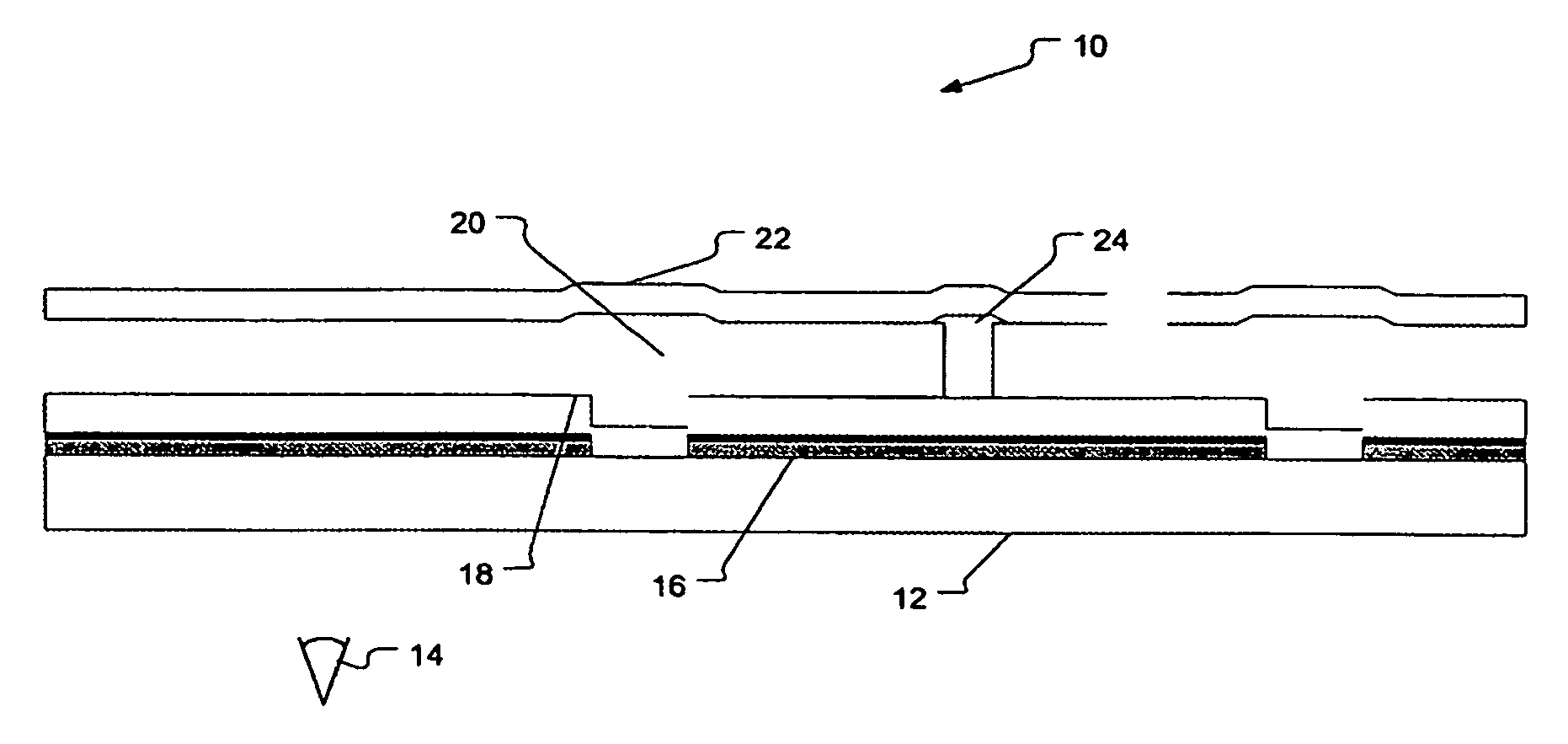
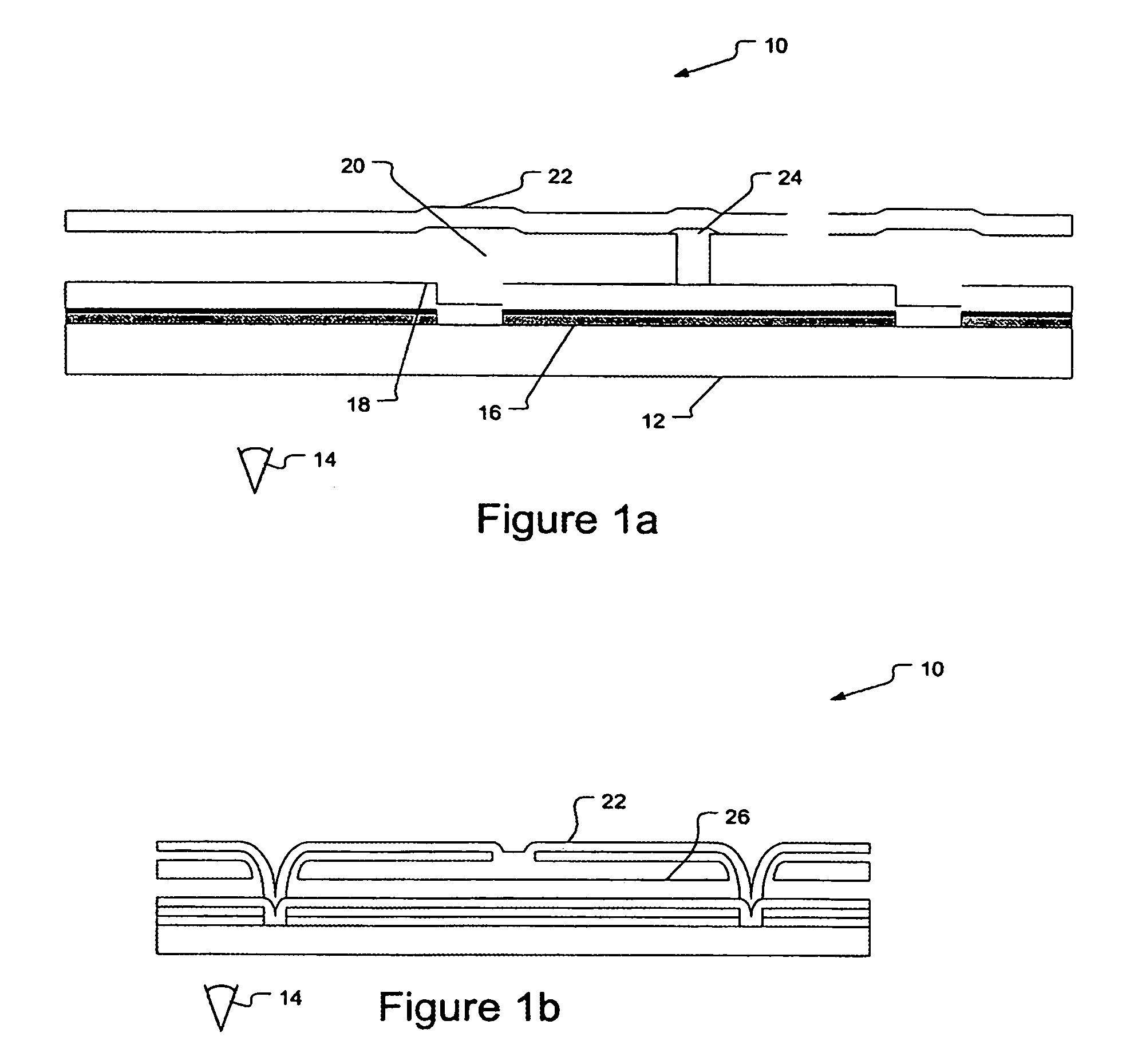
[0013]Interferometric modulators, such as the iMoD™, rely upon interference effects operating on light inside the cavity to modulate the light in accordance with image data. Cross-sectional views of such a modulator 10 are shown in FIGS. 1a and 1b. In this embodiment, the viewing surface would be at the ‘bottom’ of the picture, as shown by the viewer eye 14. The modulator array is formed on a transparent substrate 12. An optical stack 16 forms a first optically active surface that may be affected by the second optically active surface, the mechanical or mirror layer 22. A dielectric layer 18 typically protects the optical stack layer. The mechanical layer 22 is supported by posts such as 24, with the location of posts forming the individual elements of the array.

[0014]When the circuitry on the substrate, not shown, is activated in a particular region under the mechanical layer, such as that portion that is suspended over cavity 20, the mechanical layer deflects towards the optical s...


PUM


Abstract

A package is made of a transparent substrate having an interferometric modulator and a back plate. A non-hermetic seal joins the back plate to the substrate to form a package, and a desiccant resides inside the package. A method of packaging an interferometric modulator includes providing a transparent substrate and manufacturing an interferometric modulator array on a backside of the substrate. A back plate is provided and a desiccant is applied to the back plate. The back plate is sealed to the backside of the substrate with a back seal in ambient conditions, thereby forming a package

Description

BACKGROUND[0001]Interferometric modulators are spatial light modulators typically used in display applications. These modulators use interference effects to control the intensity and the color of the light seen by a viewer. One example of such a modulator is the iMoD™. The iMoD employs a cavity having at least one movable or deflectable wall. As the wall, typically comprised at least partly of metal, moves towards a front surface of the cavity, interference occurs that affects the color of light viewed at the front surface. The front surface is typically the surface where the image seen by the viewer appears, as the iMoD is a direct-view device.[0002]The front surface is transparent, as it is the portion of the device through which the viewer views the image. Manufacture of an interferometric modulator is somewhat similar to other types of devices manufactured on glass, such as liquid crystal devices (LCD). However, due to the unique nature of the device, packaging of the device has...

Claims


Application Information

Patent Timeline
IPC IPC(8): G02F1/03G02B26/00
CPCG02B26/001
Inventor PALMATEER, LAUREN FAYGALLY, BRIAN JAMESCUMMINGS, WILLIAM J.KOTHARI, MANISHCHUI, CLARENCE
Owner SNAPTRACK
Why Eureka
Try Eureka