
Desiccant for top-emitting oled

a technology of top-emitting oled and desiccant, which is applied in the direction of discharge tube/lamp details, organic semiconductor devices, discharge tubes luminescnet screens, etc., can solve the problems of high manufacturing cost, difficult to achieve hermetic sealing, and insufficient hermetic sealing, so as to prevent moisture contamination of top-emitting oled display, not risk contamination or reaction of display components, and increase the non-emitting area of the device

Active Publication Date: 2006-02-02
GLOBAL OLED TECH
View PDF12 Cites 83 Cited by
  • Summary
  • Abstract
  • Description
  • Claims
  • Application Information

AI Technical Summary

Benefits of technology

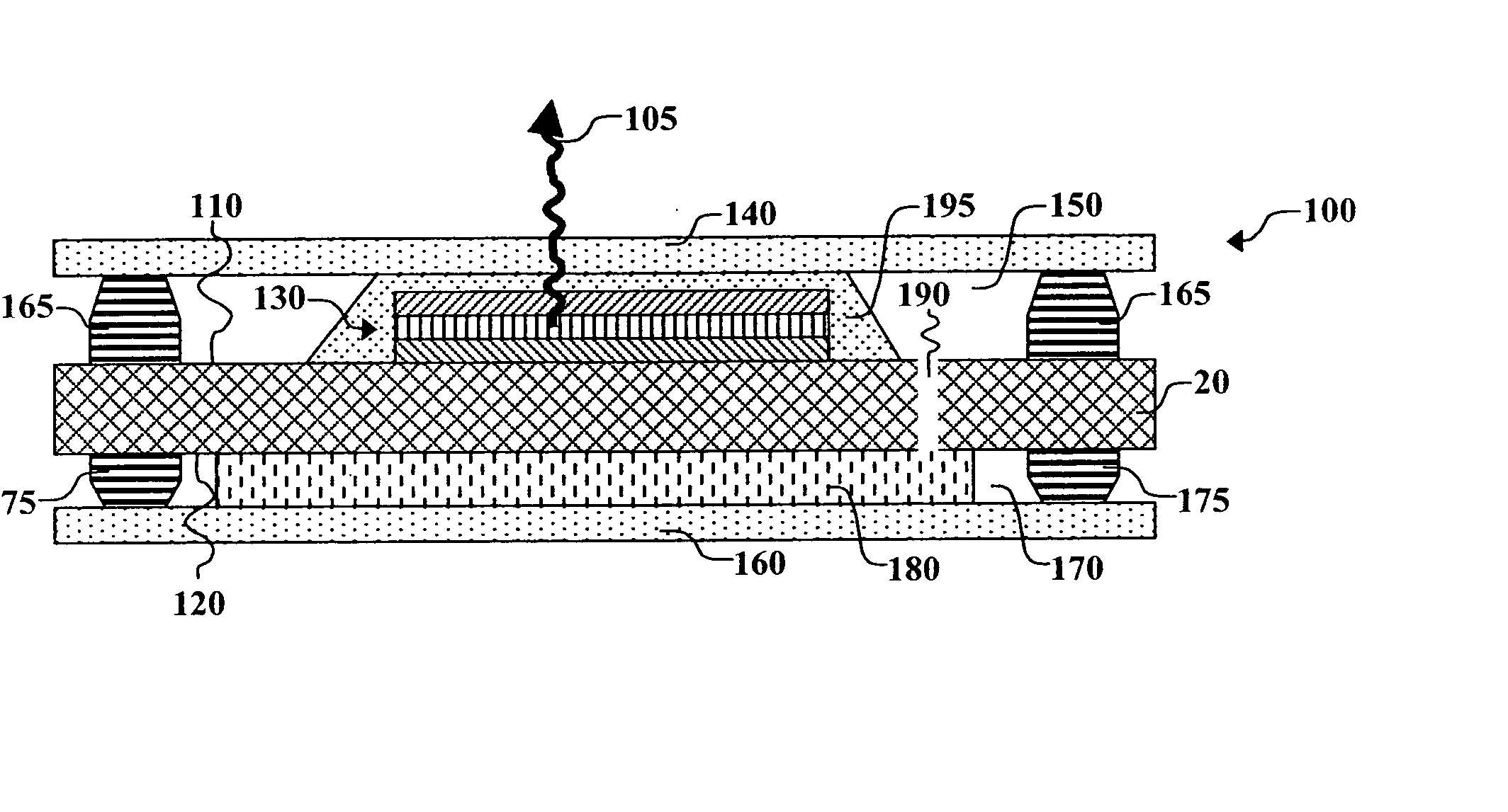
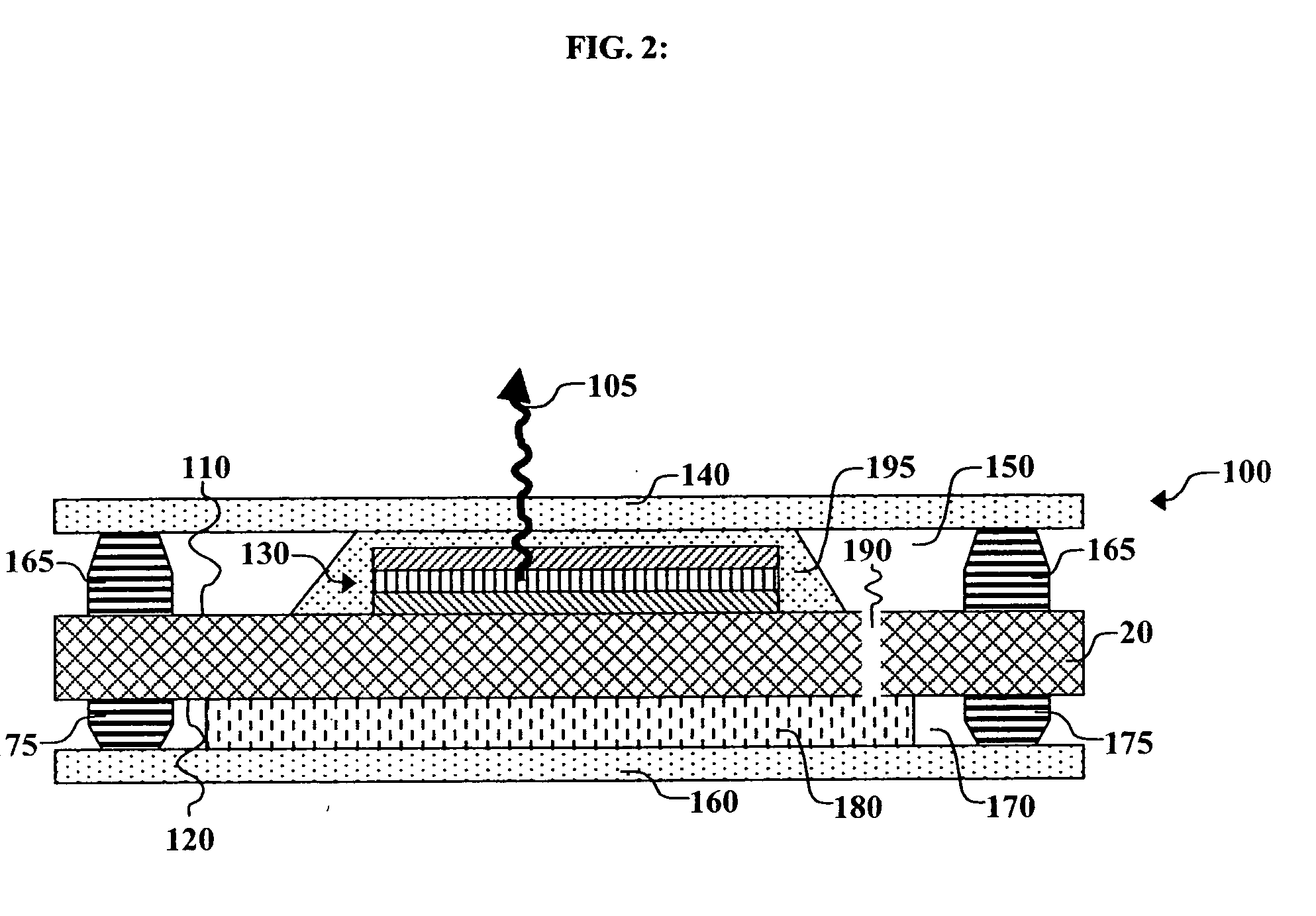
"The present invention provides a method for reducing moisture contamination in a top-emitting OLED device without interfering with the optical path of the device, without risking contamination or reaction with desiccant materials, and without increasing the non-emitting area of the device. The method involves forming a substrate with top and bottom surfaces, and then sequentially adding protective covers to the substrate surfaces to create chambers. Moisture-absorbing material is placed in the second chamber to absorb moisture in the first or second chambers. This method allows for the creation of top-emitting OLED displays without the need for completely hermetic seals, and allows for the use of a variety of desiccant materials without risking contamination or chemical reaction with the OLED organic layers and electrodes. This method can also be used in techniques for manufacturing simultaneous multiple top-emitting OLED displays."

Problems solved by technology

A common problem with OLED displays is sensitivity to water.
However, hermetic sealing is extremely difficult to achieve or expensive to manufacture, while nearly hermetic sealing is often insufficient in such moisture-sensitive devices, which often require the addition of highly active moisture-absorbing materials.
Techniques such as these require additional materials and efforts.
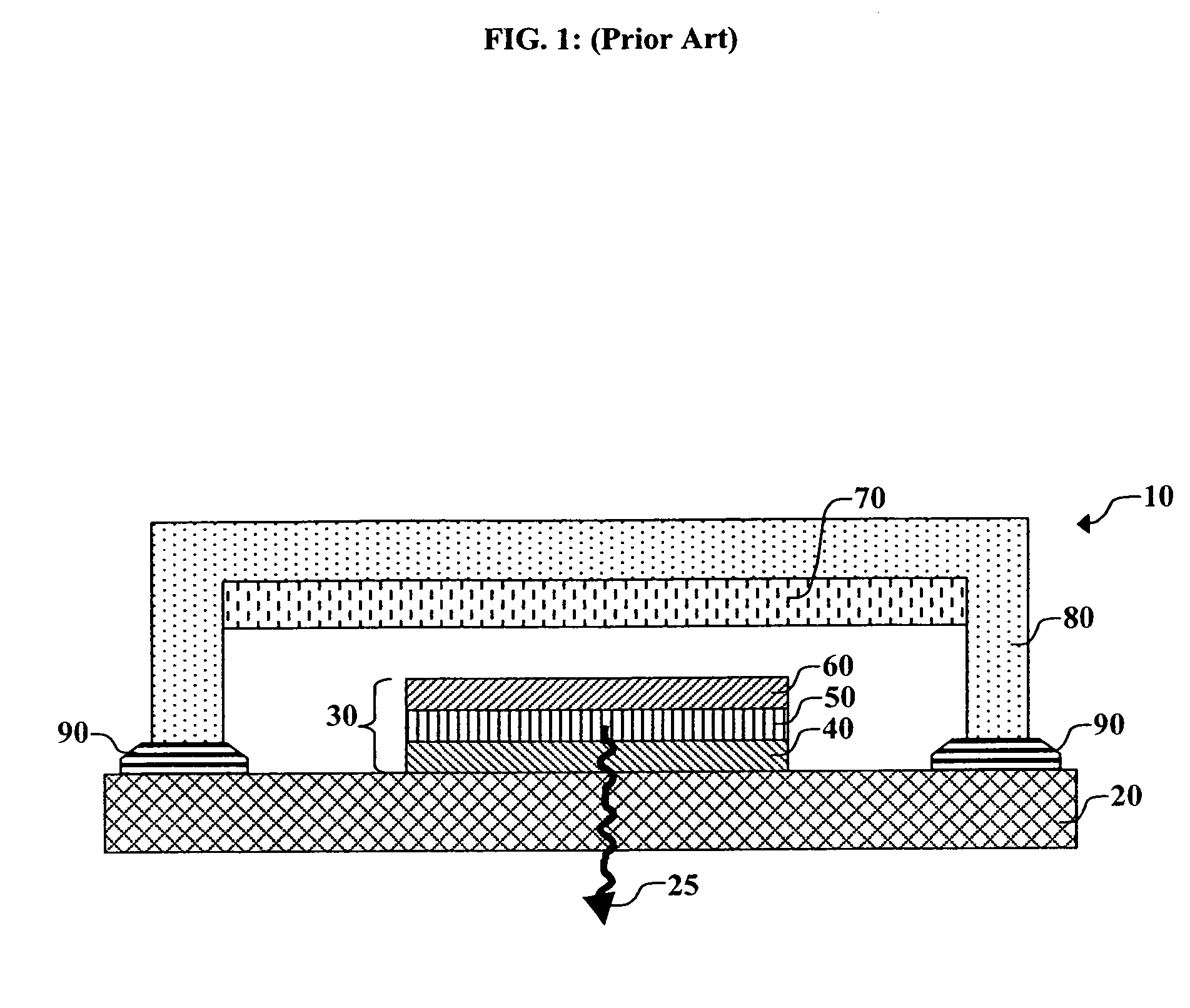
This arrangement is acceptable for bottom-emitting devices, but it cannot be used for a top-emitting OLED display, as the emission of light would be partially or completely blocked.
Therefore, it is possible that the properties of the optical path of the device will change during the device lifetime, leading to potential visual changes in the display.
This can limit the usefulness of this method.
However, this technique has the undesirable side-effect of increasing the size of the device without providing any added display area, or limiting the amount of desiccant to minimize the added display area.
For some applications, this can be unacceptable.

Method used


Image

  • Desiccant for top-emitting oled
  • Desiccant for top-emitting oled
  • Desiccant for top-emitting oled

Examples


Embodiment Construction

[0029] The term “OLED device” or “organic light-emitting display” is used in its art-recognized meaning of a display device comprising organic light-emitting diodes as pixels. A color OLED device emits light of at least one color. The term “multicolor” is employed to describe a display panel that is capable of emitting light of a different hue in different areas. In particular, it is employed to describe a display panel that is capable of displaying images of different colors. These areas are not necessarily contiguous. The term “full color” is commonly employed to describe multicolor display panels that are capable of emitting in the red, green, and blue regions of the visible spectrum and displaying images in any combination of hues. The red, green, and blue colors constitute the three primary colors from which all other colors can be generated by appropriate mixing. However, the use of additional colors to extend the color gamut of the device is possible. The term “hue” refers to...


PUM


Abstract

A method for reducing moisture contamination in a top-emitting OLED device includes providing a substrate having top and bottom surfaces; forming a top-emitting EL unit over the top surface of the substrate, wherein the EL unit produces light that is primarily not emitted through the substrate; forming first and second protective covers over the top and bottom surfaces of the substrate, respectively, and thereby defining first and second chambers, respectively; providing moisture-absorbing material in association with the second chamber; and providing communication between the first and second chambers whereby moisture in the first or second chambers is absorbed by the moisture-absorbing material.

Description

CROSS REFERENCE TO RELATED APPLICATION [0001] Reference is made to commonly assigned U.S. patent application Ser. No. 09 / 957,851, filed Sep. 21, 2001, entitled “Highly Moisture-Sensitive Eelectronic Device Element and Method for Fabrication” by Boroson et al. the disclosure of which is incorporated herein by reference.FIELD OF THE INVENTION [0002] The present invention relates to protecting OLED devices from moisture. BACKGROUND OF THE INVENTION [0003] An organic light-emitting diode device, also called an OLED device, commonly includes a substrate, an anode, a hole-transporting layer made of an organic compound, an organic luminescent layer with suitable dopants, an organic electron-transporting layer, and a cathode. OLED devices are attractive because of their low driving voltage, high luminance, wide-angle viewing and capability for full-color flat emission displays. Tang et al. described this multilayer OLED device in their U.S. Pat. Nos. 4,769,292 and 4,885,211. [0004] In a bot...

Claims


Application Information

Patent Timeline
Patent Type & Authority Applications(United States)
IPC IPC(8): H05B33/04H10K99/00
CPCH01L51/0052H01L51/0059H01L51/0062H01L51/0081H01L51/0084Y10T156/1052H01L51/0089H01L51/524H01L51/5259H01L2251/5315H01L2251/566H01L51/0085H10K85/615H10K85/631H10K85/649H10K85/324H10K85/341H10K85/342H10K85/351H10K2102/3026H10K71/851H10K59/874H10K59/871H05B33/04H10K50/841H10K50/846
Inventor BOROSON, MICHAEL L.
Owner GLOBAL OLED TECH
Learn More