Method and apparatus for removing and preventing lens surface contamination on a vehicle lens

a technology for vehicle lenses and lens surfaces, applied in vehicle cleaning, furnaces, instruments, etc., can solve the problems of reducing the distance between the reflector and the lens forming the optical device, affecting the effect of the lens surface moisture contamination, and affecting the operation of the optical device, so as to prevent the surface moisture contamination

Active Publication Date: 2017-10-24
RAYMOND LTD
View PDF17 Cites 9 Cited by
  • Summary
  • Abstract
  • Description
  • Claims
  • Application Information

AI Technical Summary

Benefits of technology

[0007]A general objective of the present invention is to remove and prevent surface moisture contamination from a lens of an optical device mounted on a frame of a vehicle. This objective is accomplished by sensing ambient air temperature and moisture content proximal to the lens, sensing the temperature of the lens, and directing moisture contamination removal gas through an air exhaust at the lens in response to the sensed temperatures and moisture content.

Problems solved by technology

Such optical devices, such as optical guidance systems are often subjected to varying atmospheric and air quality conditions.
Lenses forming part of the optical devices can be obstructed or rendered inoperative due to an accumulation of condensation and dust as a result of operating under such conditions.
An accumulation of dust, dirt, or condensation on the lens of the optical device will reduce the distance that the reflectors can be detected or cause a code to be misread.
In environments where condensation is prevalent due to the vehicle moving in and out of varying temperature and humidity zones, optical devices either cannot be used or are significantly reduced in function.
Neither of these solutions provide an efficient and cost-effective method for operation of material handling vehicles.
In addition to the cost of the cleaning procedure, the downtime required for the cleaning procedure results in a drop in vehicle productivity.

Method used


Image

  • Method and apparatus for removing and preventing lens surface contamination on a vehicle lens
  • Method and apparatus for removing and preventing lens surface contamination on a vehicle lens
  • Method and apparatus for removing and preventing lens surface contamination on a vehicle lens

Examples


Embodiment Construction

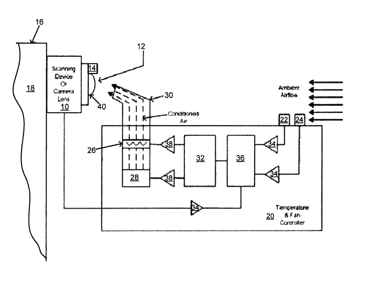
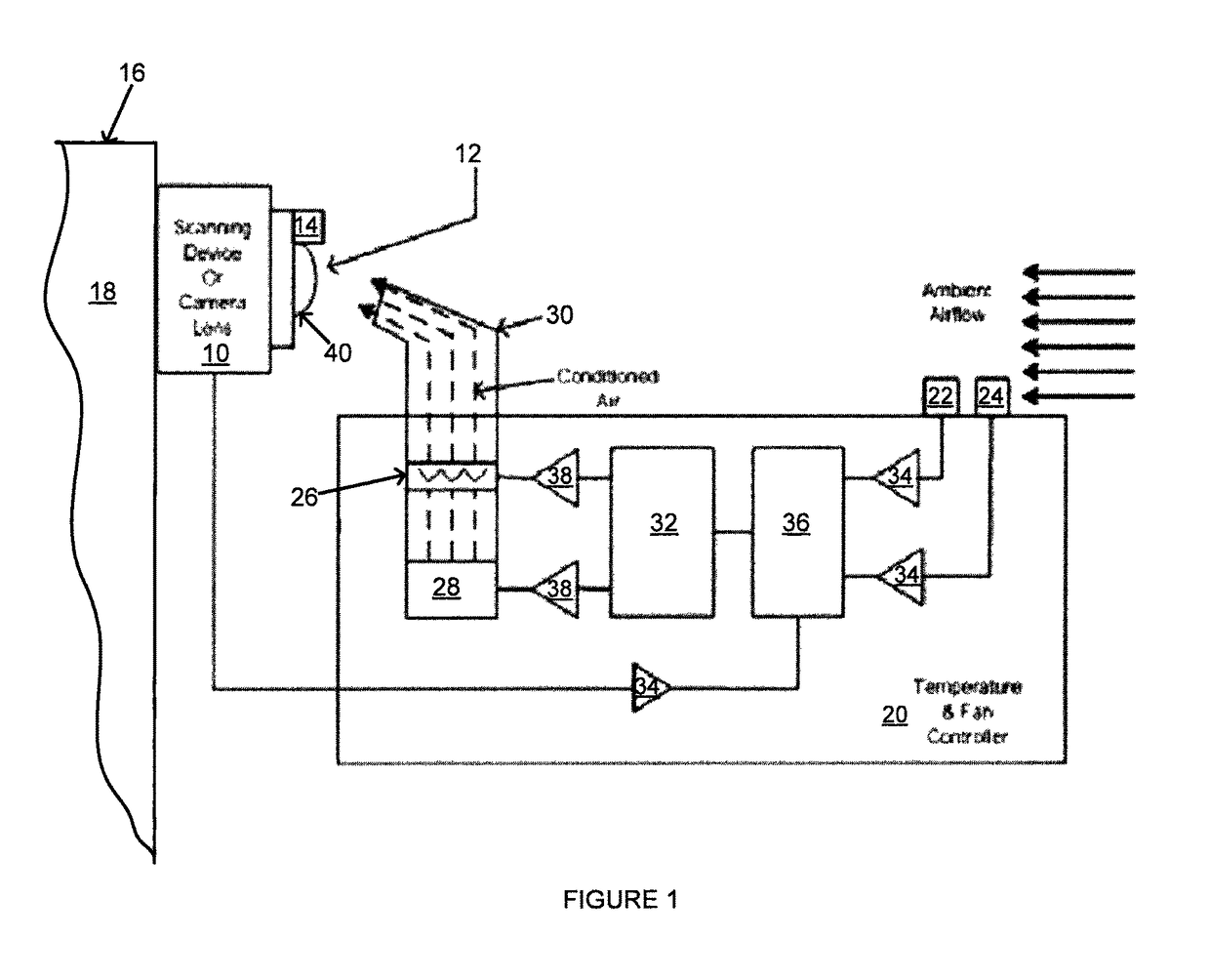
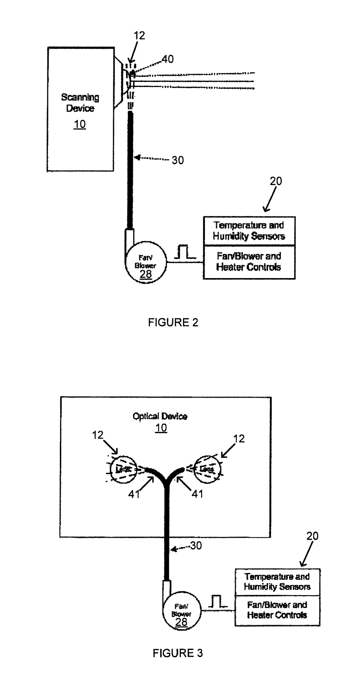
[0013]Referring to FIG. 1, an optical device 10 including a lens 12 is mounted on a frame 16 of a vehicle 18. The lens 12 of the optical device 10, such as a scanner or camera, is cleaned by a lens cleaner 20 including a lens temperature sensor 14, an ambient temperature sensor 22, a humidity sensor 24, a heater 26, a blower 28, an air exhaust 30, and a microcontroller or processor 32. The vehicle 18, such as an AGV or other industrial vehicle, may operate in environments including moisture, dust, or other airborne particles that can cause buildup on the lens 12. The lens cleaner 20 operates to prevent condensation, dust, or other particles from accumulating on the lens 12 so that the optical device 10 can obtain an unobstructed view through the lens 12 for image capture and / or scanning. More specifically, the lens cleaner 20 can continuously or periodically monitor temperature and / or humidity near the lens 12 and provide a stream of conditioned air directed toward the lens 12 to cl...


PUM


Abstract

A vehicle includes a vehicle frame and an optical device mounted on the vehicle frame. A first temperature sensor senses ambient air temperature surrounding the vehicle frame, a second temperature sensor senses a temperature of a lens of the optical device, and a humidity sensor senses moisture content of air proximal to the lens. An exhaust directs gas at the lens in response to the sensed ambient air temperature, the sensed lens temperature, and the sensed moisture content.

Description

CROSS REFERENCES TO RELATED APPLICATIONS[0001]Not ApplicableSTATEMENT REGARDING FEDERALLY SPONSORED RESEARCH[0002]Not Applicable.BACKGROUND OF INVENTION[0003]Optical devices are being incorporated into material handling industrial vehicles such as automatic guided vehicles (AGVs), operate to assist keeping the vehicles on a prescribed path. Likewise, loads picked up by material handling vehicles can be identified using optical devices to ensure the correct load is being picked up and moved by the vehicle.[0004]Such optical devices, such as optical guidance systems are often subjected to varying atmospheric and air quality conditions. Lenses forming part of the optical devices can be obstructed or rendered inoperative due to an accumulation of condensation and dust as a result of operating under such conditions. For example, an optical guidance system mounted on an AGV uses a beam of directed light to reflect back from specific known reflectors to determine the vehicle position relat...

Claims


Application Information

Patent Timeline
Patent Type & Authority Patents(United States)
IPC IPC(8): B60S1/54B60S1/56B60S1/08G02B27/00
CPCB60S1/0848G02B27/0006B60S1/54B60S1/56
Inventor FIELD, MICHAELMCCABE, PAUL P.
Owner RAYMOND LTD
Why Eureka
Try Eureka