
Transport of fluids

Inactive Publication Date: 2012-09-13
SMART SOLUTIONS & DESIGNS
View PDF0 Cites 9 Cited by
  • Summary
  • Abstract
  • Description
  • Claims
  • Application Information

AI Technical Summary

Benefits of technology

[0009]A valve to allow fluid flow through the inlet, both to increase and decrease the amount of fluid in the tank.
[0016]A backflow valve may be located downstream of the inlet to prevent any reverse flow from the tank during filling, an RPZ backflow valve is preferred. When the truck is being used to transport water the backflow valve will prevent pollution of the water main by backflow of dirty water into a hydrant.
[0024]The control unit may comprise a distinct sub-unit comprising the data acquisition device, GPS receiver and the communications equipment. This sub-unit may be wired into the vehicle ignition system; optionally via a voltage regulator, so that it is powered up when the ignition is turned on. A back-up battery may be included within the control unit to ensure the contents of volatile memory are retained after the ignition has been switched off. This also allows the control unit to transmit a status signal periodically while the truck's ignition is off; providing a check that the control system is still operational.

Problems solved by technology

A drawback of this arrangement is that the water trucks may find it necessary to travel long distances in order to fill and deliver water.

Method used


Image

  • Transport of fluids
  • Transport of fluids
  • Transport of fluids

Examples


Embodiment Construction

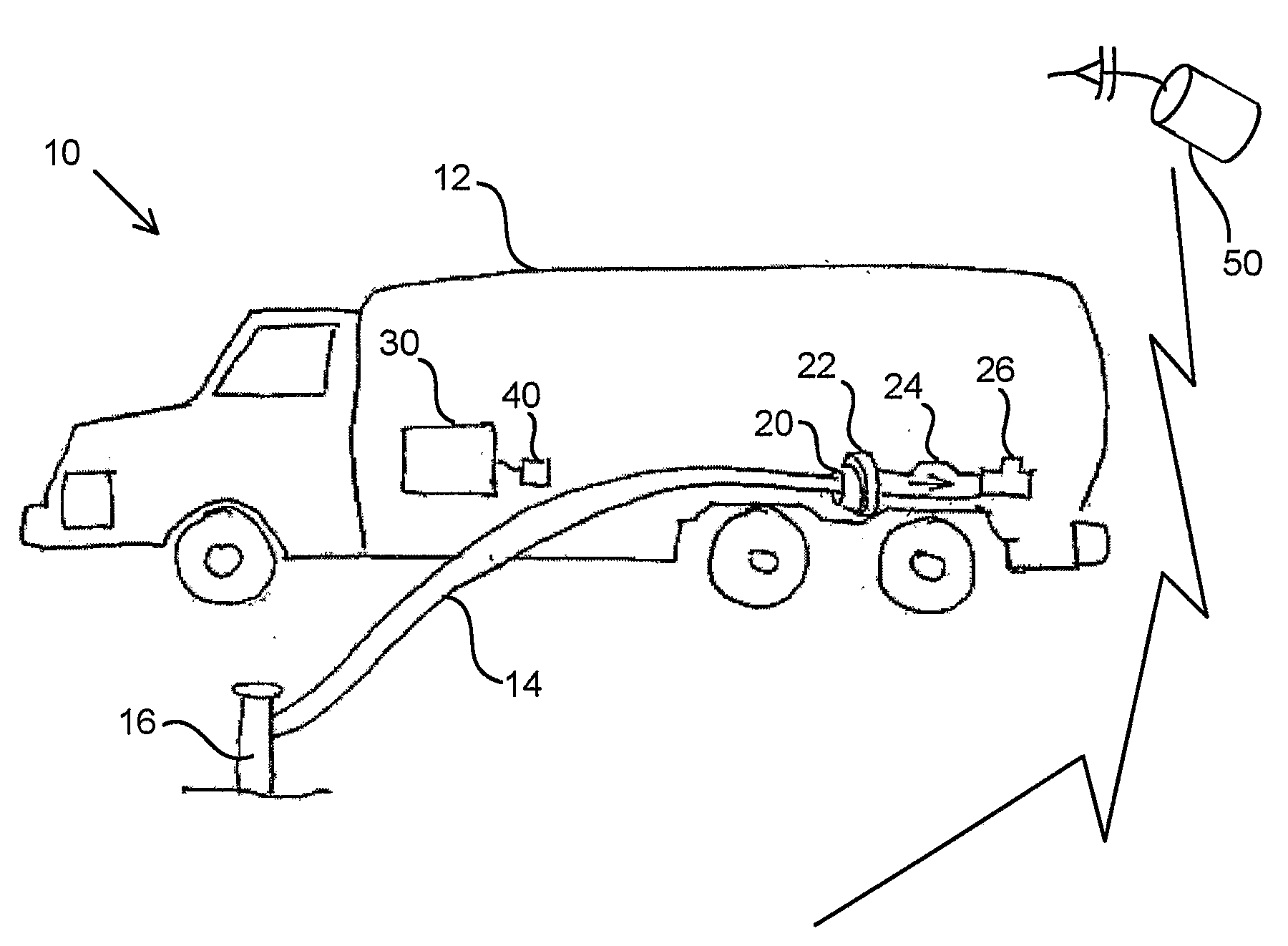
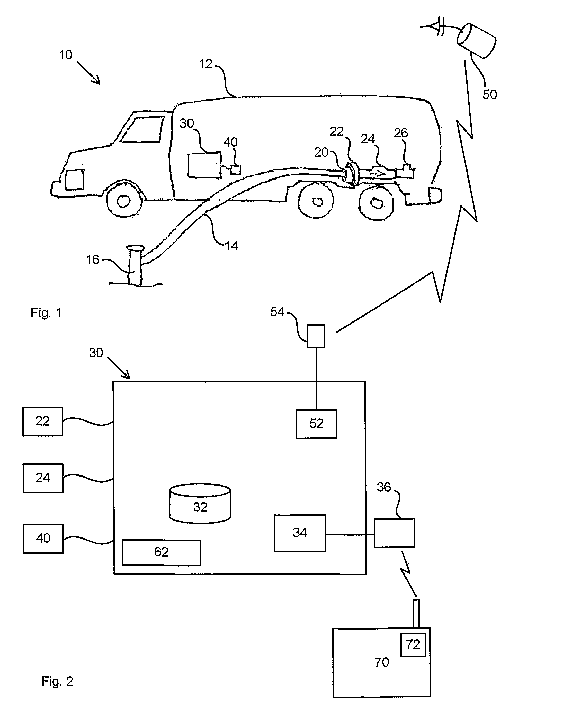
[0039]Referring first to FIG. 1, water truck 10 has a water tank 12 and a fill line 14 for filling the tank from a fire hydrant 16. On-board the truck there is a control unit 30.

[0040]Referring now to FIG. 2, the fill line 14 is attached to an inlet 20 configured for the attachment of a fire hose. Around the inlet 20 is an ultrasonic type flow meter 22 to measure flow of water into the inlet. Next there is a control valve 24 to control the rate of water flow through the inlet to fill the tank 12 (in the direction of the arrow). Following the control valve is a backflow valve 26 to prevent any reverse flow of, possibly dirty, water into the hydrant 16. The control valve 24 controls the rate of water flow into the tank. Finally a control unit 30 controls the operation of the control valve 24, records each filling event and associates a time and place with each record.

[0041]In use the control valve 24, under the control of the control unit 30, will operate to fill the tank 12. The cont...


PUM


Abstract

This invention concerns the transport of fluids. In particular in a first aspect it concerns a truck fitted with a tank and a fill line to the tank, comprising: An inlet in the fill line configured for connection to a hose that is, in use, connected to a fluid source to change the amount of fluid in the tank. A sensor to make measurements from which the amount of fluid in the tank can be determined. A valve to allow fluid flow through the inlet, both to increase and decrease the amount of fluid in the tank. And a data acquisition device to periodically record sensor measurements and to associate a time and place with each record. In a second aspect the invention concerns a control system for the truck. In a third aspect the invention concerns a control system for a fleet of trucks.

Description

TECHNICAL FIELD[0001]This invention concerns the transport of fluids. In particular in a first aspect it concerns a truck. In a second aspect the invention concerns a control system for the truck. In a third aspect the invention concerns a control system for a fleet of trucks.BACKGROUND ART[0002]The infrastructure of urban areas generally includes a reticulated main water supply network, that reaches every street and building to supply fresh water. Access to mains water is also required by fire services, and fire hydrants are provided at regular intervals throughout the mains network for fire service access. Typically the hydrants can be accessed by a standpipe or a specially designed water hose that is deployed from a fire truck.[0003]There are also a number of other reasons why water might be transported by water trucks. As a result the water authority will generally have a number of filling stations where water trucks are able to fill with fresh water from the mains. A drawback o...

Claims


Application Information

Patent Timeline
IPC IPC(8): G06F7/00F16K21/18G06Q10/00
CPCG06Q10/06Y10T137/7303B60P3/22E03B9/00F17C13/02G06Q10/00
Inventor LEIGH, JIM
Owner SMART SOLUTIONS & DESIGNS
Learn More