Desiccant air conditioning methods and systems

a technology of desiccant air and air conditioning, applied in the direction of machine operation mode, lighting and heating apparatus, heating type, etc., can solve the problems of affecting the efficiency of air conditioning. , to achieve the effect of efficient dehumidification and efficient operation

Active Publication Date: 2014-09-04
COPELAND LP
View PDF0 Cites 82 Cited by
  • Summary
  • Abstract
  • Description
  • Claims
  • Application Information

AI Technical Summary

Benefits of technology

[0006]Provided herein are methods and systems used for the efficient dehumidification of an air stream using a liquid desiccant. In accordance with one or more embodiments, the liquid desiccant is running down the face of a support plate as a falling film. In accordance with one or more embodiments, the desiccant is contained by a microporous membrane and the air stream is directed in a primarily vertical orientation over the surface of the membrane and whereby both latent and sensible heat are absorbed from the air stream into the liquid desiccant. In accordance with one or more embodiments, the support plate is filled with a heat transfer fluid that preferably flows in a direction counter to the air stream. In accordance with one or more embodiments, the system comprises a conditioner that removes latent and sensible heat through the liquid desiccant and a regenerator that removes the latent and sensible heat from the system. In accordance with one or more embodiments, the heat transfer fluid in the conditioner is cooled by a refrigerant compressor or an external source of cold heat transfer fluid. In accordance with one or more embodiments, the regenerator is heated by a refrigerant compressor or an external source of hot heat transfer fluid. In accordance with one or more embodiments, the cold heat transfer fluid can bypass the conditioner and the hot heat transfer fluid can bypass the regenerator thereby allowing independent control of supply air temperature and relative humidity. In accordance with one or more embodiments, the conditioner's cold heat transfer fluid is additionally directed through a cooling coil and the regenerator's hot heat transfer fluid is additionally directed through a heating coil. In accordance with one or more embodiments, the hot heat transfer fluid has an independent method or rejecting heat, such as through an additional coil or other appropriate heat transfer mechanism. In accordance with one or more embodiments, the system has multiple refrigerant loops or multiple heat transfer fluid loops to achieve similar effects for controlling air temperature on the conditioner and liquid desiccant concentration by controlling the regenerator temperature. In one or more embodiments, the heat transfer loops are serviced by separate pumps. In one or more embodiments, the heat transfer loops are services by a single shared pump. In one or more embodiments, the refrigerant loops are independent. In one or more embodiments, the refrigerant loops are coupled so that one refrigerant loop only handles half the temperature difference between the conditioner and the regenerator and the other refrigerant loop handles the remaining temperature difference, allowing each loop to function more efficiently.
[0010]In accordance with one or more embodiments, the indirect evaporator is used to provide heated, humidified air to a supply air stream to a space while a conditioner is simultaneously used to provide heated, humidified air to the same space. This allows the system to provide heated, humidified air to a space in winter conditions. The conditioner is heated and is desorbing water vapor from a desiccant and the indirect evaporator can be heated as well and is desorbing water vapor from liquid water. In one or more embodiments, the water is seawater. In one or more embodiments, the water is waste water. In one or more embodiments, the indirect evaporator uses a membrane to prevent carry-over of non-desirable elements from the seawater or waste water. In one or more embodiments, the water in the indirect evaporator is not cycled back to the top of the indirect evaporator such as would happen in a cooling tower, but between 20% and 80% of the water is evaporated and the remainder is discarded.
[0013]In accordance with one or more embodiments, a conditioner receives an air stream that is pushed through the conditioner by a fan resulting in a pressure in the conditioner that is above the ambient pressure. In one or more embodiments, such positive pressure aids in ensuring that a membrane is held flat against a plate structure. In one or more embodiments, a regenerator receives an air stream that is pushed through the regenerator by a fan resulting in a pressure in the regenerator that is above ambient pressure. In one or more embodiments, such positive pressure aids in ensuring that a membrane is held flat against a plate structure.

Problems solved by technology

Conventional vapor compression systems have only a limited ability to dehumidify and tend to overcool the air, oftentimes requiring energy intensive reheat systems, which significantly increase the overall energy costs, because reheat adds an additional heat-load to the cooling system.
However such super-hydrophobic membranes are typically hard to adhere to and are easily subject to damage.
Several failure modes can occur: if the desiccant is pressurized the bonds between the membrane and its support structure can fail, or the membrane's pores can distort in such a way that they no longer are able to withstand the liquid pressure and break-through of the desiccant can occur.
Furthermore if the desiccant crystallizes behind the membrane, the crystals can break through the membrane itself creating permanent damage to the membrane and causing desiccant leaks.
And in addition the service life of these membranes is uncertain, leading to a need to detect membrane failure or degradation well before any leaks may even be apparent.

Method used


Image

  • Desiccant air conditioning methods and systems
  • Desiccant air conditioning methods and systems
  • Desiccant air conditioning methods and systems

Examples


Embodiment Construction

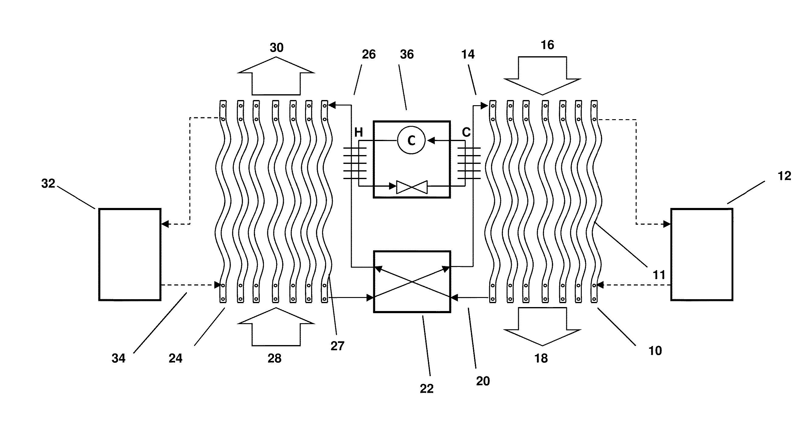
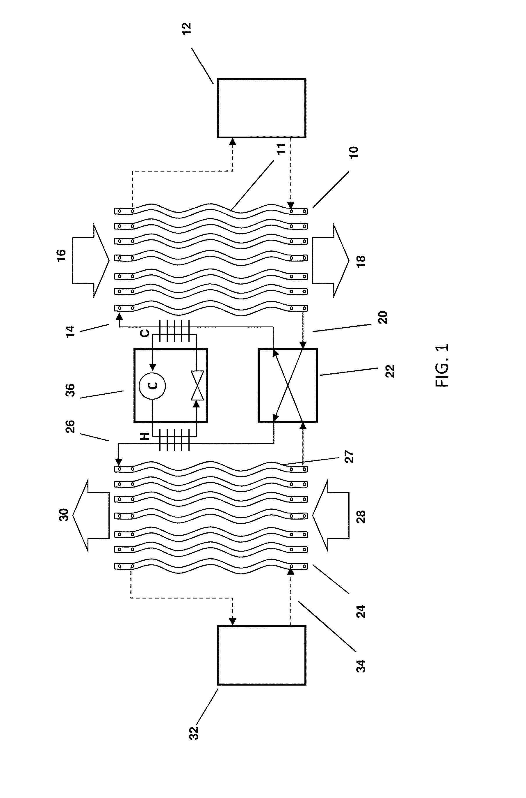
[0044]FIG. 1 depicts a new type of liquid desiccant system as described in more detail in U.S. Patent Application Publication No. 2012 / 0125020 entitled METHODS AND SYSTEMS FOR DESICCANT AIR CONDITIONING USING PHOTOVOLTAIC-THERMAL (PVT) MODULES. A conditioner 10 comprises a set of plate structures 11 that are internally hollow. A cold heat transfer fluid is generated in cold source 12 and entered into the plates. Liquid desiccant solution at 14 is brought onto the outer surface of the plates 11 and runs down the outer surface of each of the plates 11. The liquid desiccant runs behind a thin membrane that is located between the air flow and the surface of the plates 11. Outside air 16 is now blown through the set of wavy plates 11. The liquid desiccant on the surface of the plates attracts the water vapor in the air flow and the cooling water inside the plates 11 helps to inhibit the air temperature from rising. The treated air 18 is put into a building space.

[0045]The liquid desiccan...


PUM


Abstract

A desiccant air conditioning system for treating an air stream entering a building space, including a conditioner configured to expose the air stream to a liquid desiccant such that the liquid desiccant dehumidifies the air stream in the warm weather operation mode and humidifies the air stream in the cold weather operation mode. The conditioner includes multiple plate structures arranged in a vertical orientation and spaced apart to permit the air stream to flow between the plate structures. Each plate structure includes a passage through which a heat transfer fluid can flow. Each plate structure also has at least one surface across which the liquid desiccant can flow. The system includes a regenerator connected to the conditioner for causing the liquid desiccant to desorb water in the warm weather operation mode and to absorb water in the cold weather operation mode from a return air stream.

Description

CROSS-REFERENCE TO RELATED APPLICATION[0001]This application claims priority from U.S. Provisional Patent Application No. 61 / 771,340 filed on Mar. 1, 2013 entitled METHODS FOR CONTROLLING 3-WAY HEAT EXCHANGERS IN DESICCANT CHILLERS, which is hereby incorporated by reference.BACKGROUND[0002]The present application relates generally to the use of liquid desiccants to dehumidify and cool, or heat and humidify an air stream entering a space. More specifically, the application relates to the control systems required to operate 2 or 3 way liquid desiccant mass and heat exchangers employing micro-porous membranes to separate the liquid desiccant from an air stream. Such heat exchangers can use gravity induced pressures (siphoning) to keep the micro-porous membranes properly attached to the heat exchanger structure. The control systems for such 2 and 3-way heat exchangers are unique in that they have to ensure that the proper amount liquid desiccant is applied to the membrane structures wit...

Claims


Application Information

Patent Timeline
Patent Type & Authority Applications(United States)
IPC IPC(8): F25B29/00
CPCF25B29/006F24F3/1417F25B25/005F25B2339/047F24F3/1429F24F2003/144F24F2003/1458F24F2012/007F24F2203/1008F24F11/81F24F2003/1435F24F2203/021
Inventor VANDERMEULEN, PETER F.LAFLAMME, ARTHURALLEN, MARKDOODY, ROBERTPITCHER, DAVID
Owner COPELAND LP
Why Eureka
Try Eureka