Sensor storage device

A storage device and sensor technology, used in containers, packaged food, transportation and packaging, etc., can solve problems such as lack of or lack of earthquake resistance.

Active Publication Date: 2019-05-17
HARBIN UNIV
View PDF11 Cites 10 Cited by
  • Summary
  • Abstract
  • Description
  • Claims
  • Application Information

AI Technical Summary

Problems solved by technology

[0009] In view of the above situation, in order to overcome the defects of the prior art, the present invention provides a sensor storage device, which effectively solves the problem that the existing sensor storage device does not have the ability to automatically control temperature and humidity, and does not have a certain anti-seismic ability.

Method used


Image

  • Sensor storage device
  • Sensor storage device
  • Sensor storage device

Examples


Embodiment 1

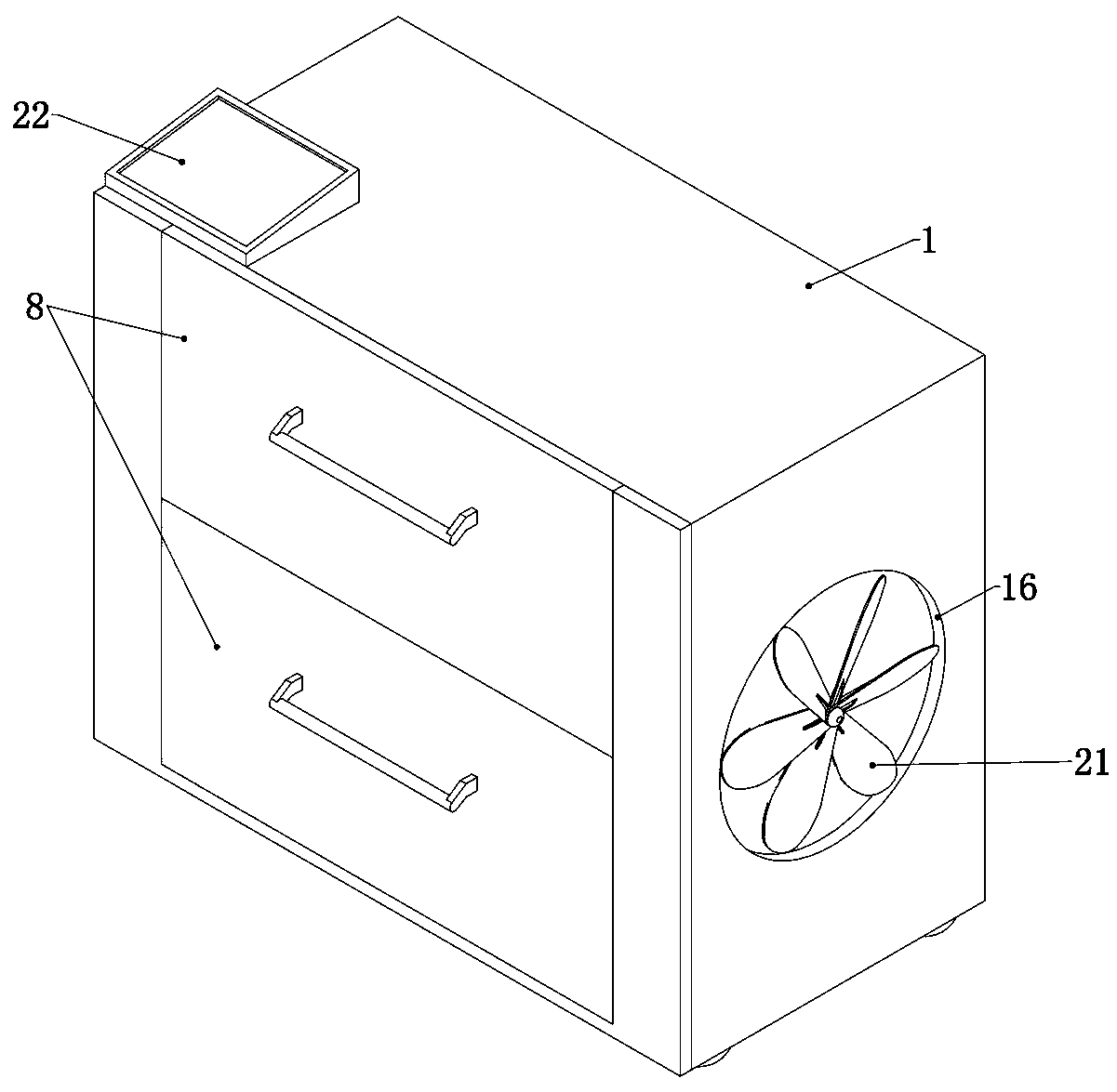
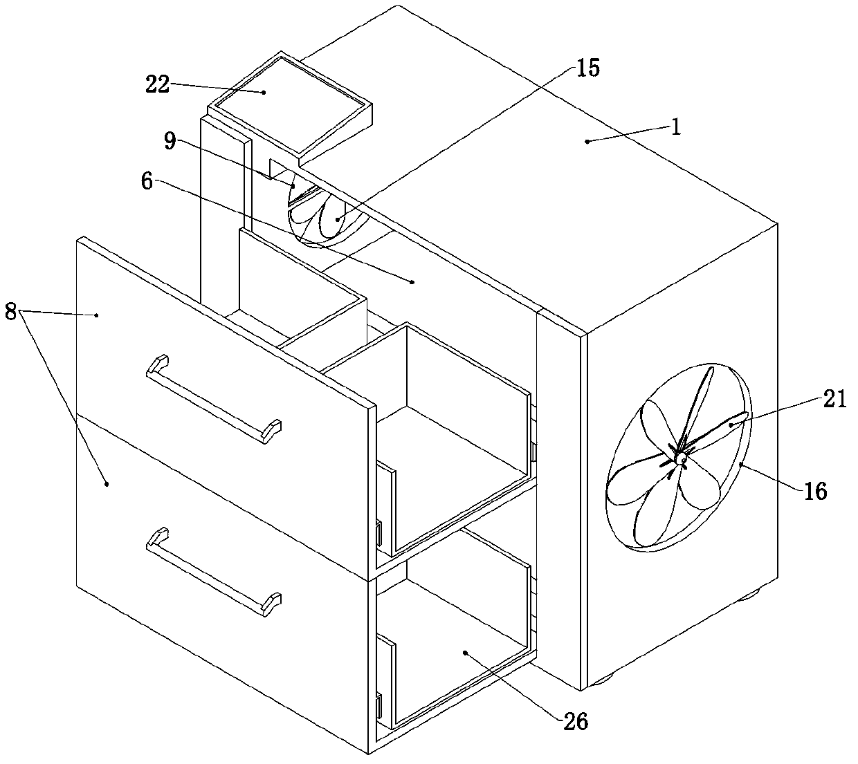
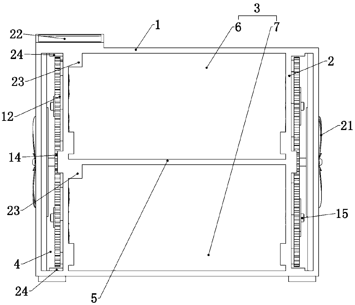
[0036] Embodiment 1, the present invention is a sensor storage device, including a hollow box 1, the box 1 is a common hollow square box 1, which is used to provide a fixed foundation for subsequent structures, in order to prevent the occurrence of ground water flooding In the case of the box body 1, the four corners of the lower end surface of the box body 1 are fixedly connected with outriggers to ensure that the support is firm and not easy to slip. The height of the four outriggers should be low and made of rubber material. The box body 1 can also provide a fixed foundation for the subsequent structure. It is characterized in that the left and right sides of the box body 1 are fixedly connected with vertical partitions 2, and the two vertical partitions 2 divide the interior of the box body 1. It is a storage room 3 and two circulation rooms 4 located between the two vertical partitions 2, the storage room 3 is used to store various types of sensors, and the circulation roo...

Embodiment 2

[0038] Embodiment 2. On the basis of Embodiment 1, in order to better realize the circulation and drying of the air in the box body 1, this embodiment provides a specific method. Specifically, each of the through holes 9 There are electric small fans 15 fixedly connected inside, and the four electric small fans 15 are connected to an external power supply through wires, and a storage battery can also be fixedly installed in the box body 1 and connected to the storage battery. The electric small fans 15 It can be a common electric fan, which has its own motor and can rotate when the motor is powered on. The motor can be fixedly connected to the vertical partition 2 and fixedly connected to the through hole 9 cross the beam, and the motor is fixedly installed on the cross beam, and the electric small fan 15 should also be electrically connected with the control system, that is, when the control system controls two of the drive When the motor works so that the four through holes ...

Embodiment 3

[0039] Embodiment 3, on the basis of Embodiment 1, ventilation holes 16 are provided on the left and right side walls of the box body 1. Because the storage environment of the sensor requires that the temperature should not be too high, openings are made on both side walls of the box body 1. Ventilation holes 16, so that the temperature inside the box body 1 can be kept consistent with the outside world, then when the control system controls the drive motor to work and open the four through holes 9, the device becomes the upper storage room 6. The air circulation between the lower storage room 7 and the outside ensures that the air humidity in the upper storage room 6 and the lower storage room 7 is consistent with the outside air humidity.


PUM


Abstract

The invention relates to a sensor storage device. The problems that an existing sensor storage device does not have the temperature and humidity automatic control capability and does not have certainanti-seismic capability are effectively solved. According to the solving technical scheme, the sensor storage device comprises a hollow box, the left side and the right side inside the box are fixedlyconnected with vertical partition plates correspondingly, the two vertical partition plates partition the interior of the box into a storage chamber and two circulation chambers which are located between the two vertical partition plates, the storage chamber is partitioned into an upper storage chamber and a lower storage chamber by a transverse partition plate fixedly connected into the box, storage plates are connected into the upper storage chamber and the lower storage chamber in a front-rear sliding mode correspondingly, through holes are formed in the left side walls and the right sidewalls of the upper storage chamber and the lower storage chamber correspondingly, and each through hole is provided with a door opening and closing mechanism. The sensor storage device is concise in structure, the temperature and the humidity in the box can be automatically adjusted, the function is perfect, the automation degree is high, and practicability is high.

Description

technical field [0001] The invention relates to the technical field of storage devices, in particular to sensor storage devices. Background technique [0002] In modern industrial production, especially in the automated production process, various sensors are used to monitor and control various parameters in the production process, so that the equipment can work in a normal or optimal state, and the product can achieve the best quality. Therefore, it can be said that without a large number of excellent sensors, modern production will lose its foundation. Therefore, the storage of sensors is very important. [0003] The sensor must be stored in a clean, ventilated, non-corrosive gas warehouse; unless otherwise specified, the temperature and relative humidity of the warehouse must meet the following requirements: [0004] Temperature: -5~30°C, the general sensor storage requirement is 5°C to 70°C, but combined with the humidity requirements, the storage temperature is best s...

Claims


Application Information

Patent Timeline
Patent Type & Authority Applications(China)
IPC IPC(8): B65D81/18B65D81/34B65D81/26B65D85/42
Inventor 王冰刘兴国张震宇戴冰张洪泉
Owner HARBIN UNIV
Why Eureka
Try Eureka