Hydronic rooftop cooling systems

a technology of rooftop cooling and packaged cooling, which is applied in the field of packaged rooftop cooling units, can solve the problems of reducing cooling efficiency by as much as 20%, and achieve the effects of improving rtu efficiency, enhancing rtu efficiency, and improving latent cooling control

Inactive Publication Date: 2008-01-29
DAVIS ENERGY GROUP
View PDF9 Cites 45 Cited by
  • Summary
  • Abstract
  • Description
  • Claims
  • Application Information

AI Technical Summary

Benefits of technology

[0013]This application presents new RTU designs that include evaporative cooling of both ventilation air and a condensing refrigerant, as well as other features, to significantly improve RTU efficiency.
[0014]In an exemplary embodiment of the invention, RTU efficiency is enhanced, particularly in dry climates, by better control of latent cooling that occurs when cooling coil surface temperatures are below the dew point temperature of air crossing an evaporator coil. In humid climates, substantial latent cooling is desirable, and often necessary to reduce the humidity of indoor air. However, in many dry climates, unnecessary latent cooling occurs that reduces cooling efficiency by as much as 20%. Better design and variable speed airflow and multiple evaporator coils with valved refrigerant controls to vary coil surface temperatures can increase cooling efficiency, and cold water condensed at the evaporator can be drained or pumped into the evaporative cooling reservoir to improve evaporative cooling effectiveness.
[0015]In various exemplary embodiments of the invention, improved RTU's that incorporate dual evaporative cooling systems that can recover heat from exhaust air, reduce latent cooling, and facilitate reduced blower speeds, are provided. In addition, improved RTU's that can deliver non-compressor cooling at appropriate times in dry climates when wet bulb temperatures are low, are also provided. These novel RTU's are particularly valuable if such non-compressor cooling process cools water that can be circulated through a thermal mass, such as concrete slabs, to pre-cool the building structure.

Problems solved by technology

However, in many dry climates, unnecessary latent cooling occurs that reduces cooling efficiency by as much as 20%.

Method used


Image

  • Hydronic rooftop cooling systems
  • Hydronic rooftop cooling systems
  • Hydronic rooftop cooling systems

Examples


Embodiment Construction

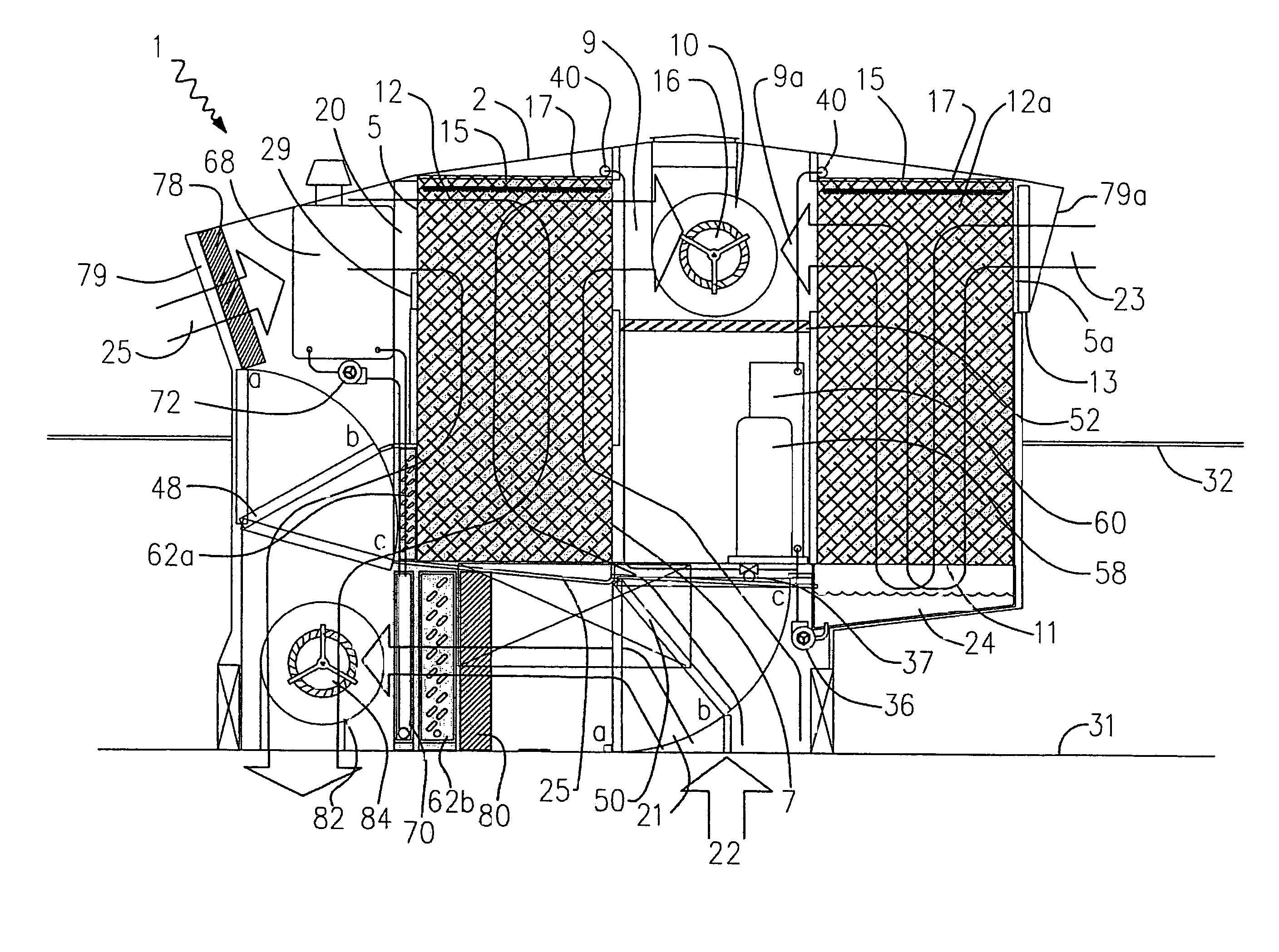
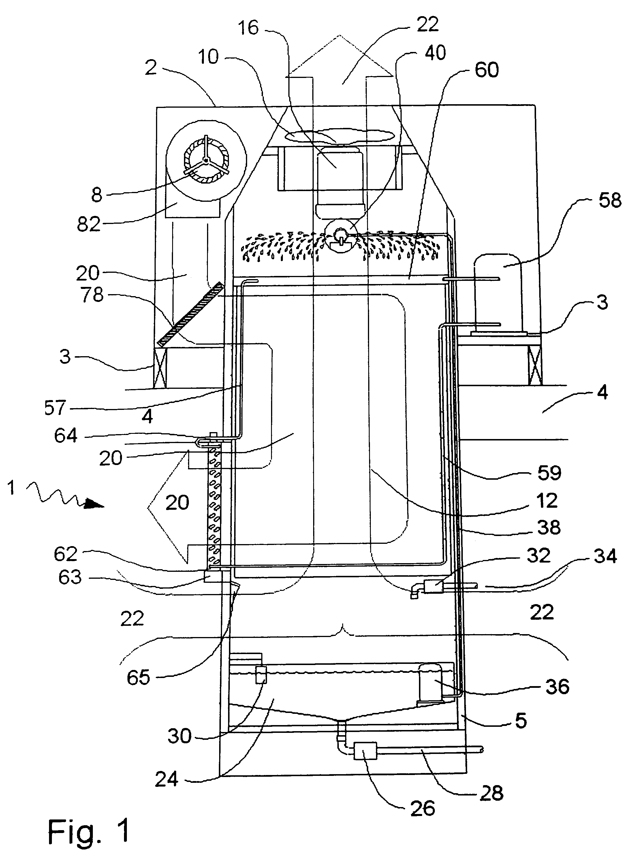
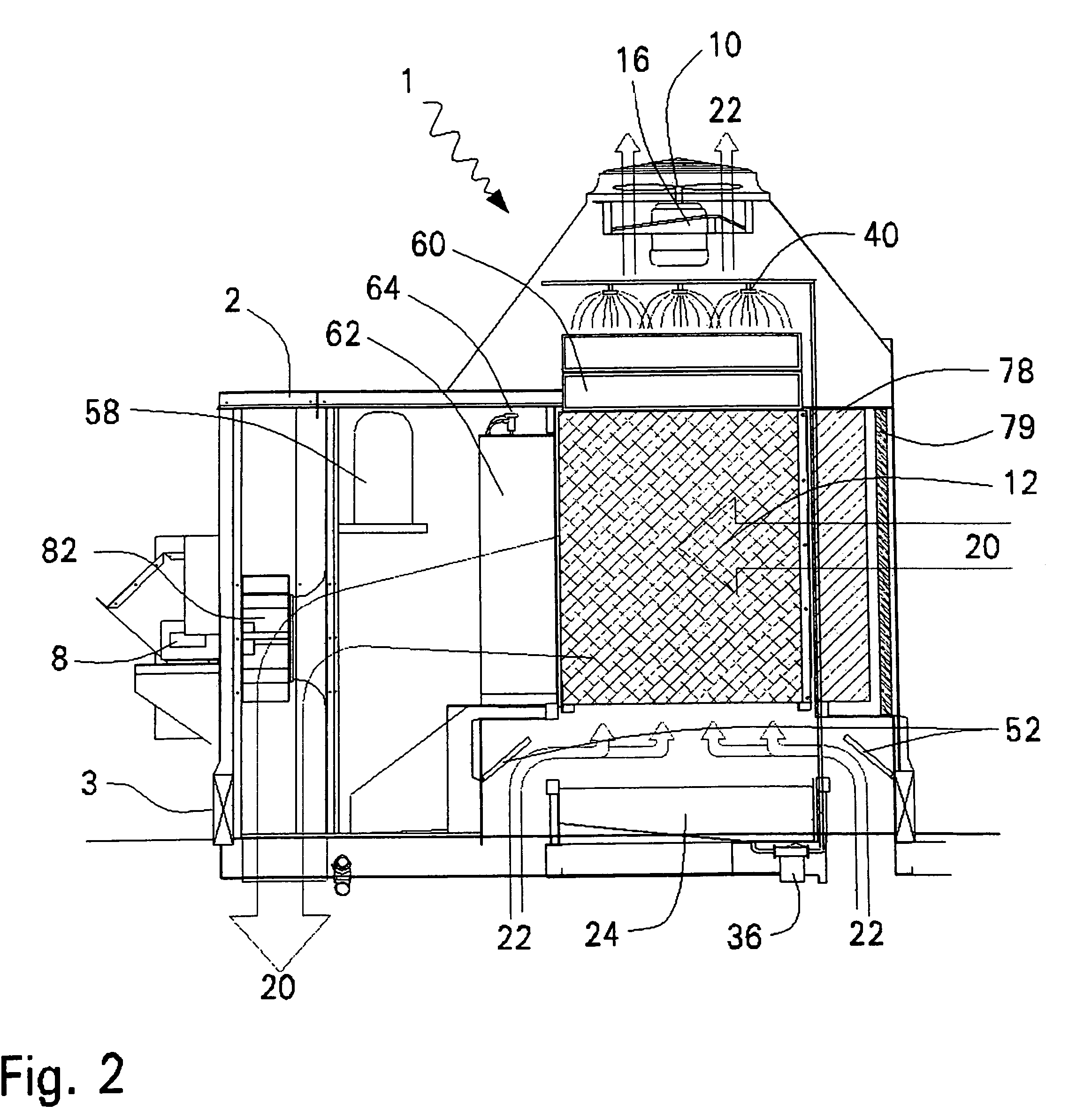
[0023]Exemplary embodiments of the present invention are described hereafter with reference to the Figures. The exemplary embodiments may include the following:[0024]1. evaporative cooling sub-systems including an indirect evaporative heat exchanger, a water reservoir, a pump, a water distribution system, an exhaust fan, a water supply system, and a reservoir drainage system;[0025]2. refrigeration sub-systems including a compressor, a condenser, an evaporator, and an expansion device, to cool supply air for a building; and[0026]3. air supply sub-systems including outdoor air inlets, a supply blower, and an air filter.

[0027]FIGS. 1 and 2 show exemplary embodiments that supply 100% conditioned outdoor air to a building, and are “cooling only” units, i.e., without space heating components. In the 100% outdoor air system, an amount of air equal to the supply air quantity must leave the building (ideally through the rooftop unit), and no building air returns to mix with the supply air 10...


PUM


Abstract

A roof top cooling unit has an evaporative cooling section that includes at least one evaporative module that pre-cools ventilation air and water; a condenser; a water reservoir and pump that captures and re-circulates water within the evaporative modules; a fan that exhausts air from the building and the evaporative modules and systems that refill and drain the water reservoir. The cooling unit also has a refrigerant section that includes a compressor, an expansion device, evaporator and condenser heat exchangers, and connecting refrigerant piping. Supply air components include a blower, an air filter, a cooling and / or heating coil to condition air for supply to the building, and optional dampers that, in designs that supply less than 100% outdoor air to the building, control the mixture of return and ventilation air.

Description

[0001]This application claims the benefits of U.S. Provisional Patent Application No. 60 / 502,251 filed Sep. 12, 2003, the entire disclosure of which is herein incorporated by reference.[0002]This invention was made with Government support under Contract #DE-FC26-00NT40991 awarded by the United States Department of Energy. The Government has certain fights in the invention.BACKGROUND OF THE INVENTION[0003]1. Field of Invention[0004]This invention relates to improvements in packaged rooftop cooling units, and particularly to units that incorporate evaporative cooling to improve the efficiency, and reduce electrical demand of packaged rooftop cooling systems.[0005]2. Description of Related Art[0006]Most new low-rise non-residential buildings in the U.S. are cooled with packaged rooftop units (“RTU's”) that include one or more compressors, a condenser section that includes one or more air-cooled condensing coils and condenser fans, an evaporator coil, a supply blower, an intake location...

Claims


Application Information

Patent Timeline
Patent Type & Authority Patents(United States)
IPC IPC(8): F28D5/00F24F1/0043F24F3/044F24F5/00F24F12/00
CPCF24F3/044F24F5/0035F24F12/006F28D5/00F24F2001/0092Y02B30/563Y02B30/545Y10S62/16F24F2012/007F24F1/0007Y02B30/54Y02B30/56F24F1/0043
Inventor BOURNE, RICHARD C.LEE, BRIAN ERICBERMAN, MARK J.
Owner DAVIS ENERGY GROUP
Why Eureka
Try Eureka