Light emitting device

a technology of light emitting device and discharge tube, which is applied in the direction of instruments, discharge tube luminescnet screens, lighting and heating apparatus, etc., can solve the problems of promoting element degradation, difficult to have complete cut off from moisture and oxygen, and changing film quality and material itsel

Inactive Publication Date: 2002-05-16
SEMICON ENERGY LAB CO LTD
View PDF40 Cites 77 Cited by
  • Summary
  • Abstract
  • Description
  • Claims
  • Application Information

AI Technical Summary

Problems solved by technology

If thermal setting resins are used, then the organic EL layers are also heated during setting, and changes in film quality and degradation of the material itself develop.
However, even if the EL elements are cut off from the outside atmosphere by using the light setting resins, it is difficult to have complete cut off from moisture and oxygen.
For example, a large amount of dark spots develop with organic EL elements sealed by a UV setting resin when they are held under high temperature and high humidity, thereby promoting the element degradation.
However, if drying agents which physically absorb moisture are used, such as the zeolites and silica gels shown in Reference 3, then the moisture which has been absorbed is emitted due to Joule heat generated when the organic EL elements emit light, and there is a danger that the growth of dark spots cannot be sufficiently controlled.
However, if fine powders as drying agents, in particular fine powders of materials containing alkaline metals or alkaline-earth metals are taken into the clean room, they may greatly influence the cleanliness within the clean room.
Namely, the fine powders cause damage to wiring pattern formation.
Alkaline metal ions generated due to the fine powders cause phenomena such as an increase in the speed of oxidation, for example, and are a cause of defective parts.
However, it is difficult to completely prevent indirect contamination (cross contamination) through the substrate when the substrate...

Method used


Image

  • Light emitting device
  • Light emitting device
  • Light emitting device

Examples


embodiment 1

[0075] [Embodiment 1]

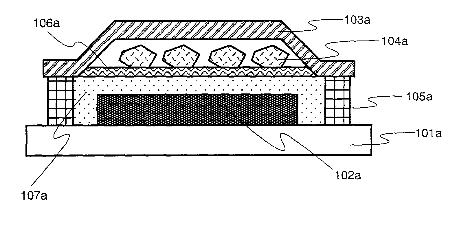
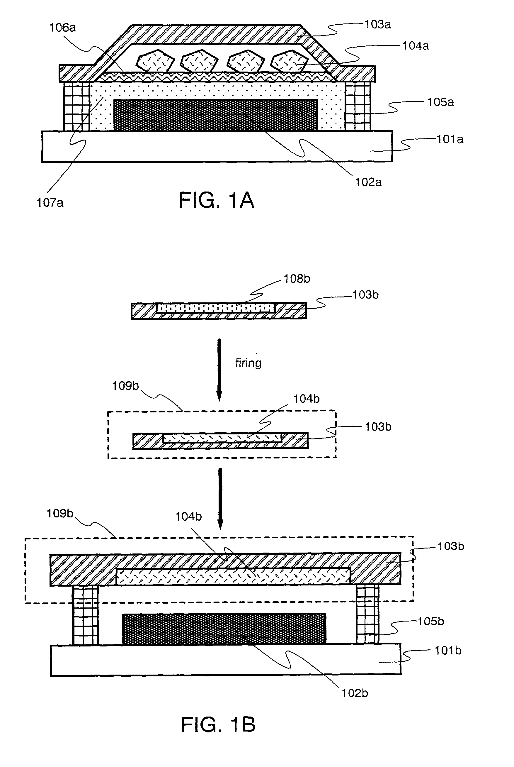
[0076] A specific example of a light emitting device in which organic EL elements are formed within a container cut off from the atmosphere, and in addition, a bulk porous body of a chemical absorption drying agent is sealed within the container is shown in embodiment 1, as shown in FIG. 1A in the embodiment mode of the present invention. FIG. 4 shows the structure. Note that the alkaline-earth metal compound calcium oxide (CaO) is used as the drying agent.

[0077] First, a film is formed on a glass substrate 401 by sputtering ITO as a transparent electrode. This is used as an anode 402. Next, for film formation of an organic EL layer 403, the aromatic amine compound shown by Chem. 2 below (hereafter referred to as -NPD) which is formed with a thickness of 50 nm as a hole transporting layer 403a, and the aluminum chelate complex expressed by Chem. 3 below (hereafter referred to as Alq.sub.3) which is formed with a thickness of 70 nm as an electron transporting and...

embodiment 2

[0082] [Embodiment 2]

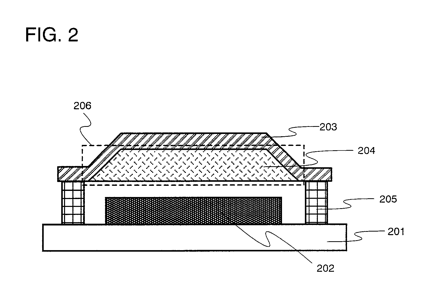
[0083] A specific example is shown in Embodiment 2 of a light emitting device in which a chemical absorption drying agent is formed into a porous film shape within a container cut off from the atmosphere, and organic EL elements are formed within the container, as shown in FIG. 2 in the embodiment mode of the present invention. The structure is shown in FIG. 5. A sol-gel method is used as the method of forming the porous film. The alkaline-earth metal oxide barium oxide is used as the porous film material.

[0084] First, a film is formed on a glass substrate 501 by sputtering ITO as a transparent electrode. This is sued as an anode 502. Next, for film formation of an organic EL layer 503, .alpha.-NPD formed with a thickness of 50 nm as a hole transporting layer 503a, and Alq.sub.3 formed with a thickness of 70 nm as an electron transporting and light emitting layer 503b, are laminated by vacuum evaporation. In addition, ytterbium is formed into a 400 nm thick film...

embodiment 3

[0087] [Embodiment 3]

[0088] In this embodiment, a light emitting device including an organic EL element disclosed in the present invention will be described. FIG. 6 is a sectional view of an active matrix type light emitting device using the organic EL element of the present invention. Incidentally, although a thin film transistor (hereinafter referred to as a TFT) is used here as an active element, a MOS transistor may be used.

[0089] Besides, although a top gate TFT (specifically, a planar TFT) is exemplified as a TFT, a bottom gate TFT (typically, an inverted stagger TFT) can also be used.

[0090] In FIG. 6, reference numeral 601 designates a substrate, and the substrate transparent to visible light is used here. Specifically, a glass substrate, a quartz substrate, a crystallized glass substrate, or a plastic substrate (including a plastic film) may be used. Incidentally, the substrate 601 also includes an insulating film provided on the surface of the substrate.

[0091] A pixel porti...


PUM


Abstract

A drying agent enclosed in an organic EL element is sealed with a shape with which particulate contamination becomes less than that of a conventional shape, while still capable of showing a moisture absorption capacity similar to that of a fine powder. A light emitting device, and an electronic device, having long life and having less particulate contamination than in a device manufactured by conventional processes, are provided by using the organic EL element. The drying agent, made from a compound capable of chemically absorbing moisture, is formed as a bulk porous body or a porous film, and is formed along with the organic EL elements within a container cut off from the atmosphere. In addition, the light emitting device and the electronic device are manufactured using the organic EL elements.

Description

[0001] 1. Field of the Invention[0002] The present invention relates to a light emitting device that uses an element having an anode, a cathode, and a film containing an organic compound in which EL (electroluminescence, luminescence which develops by the application of an electric field) is obtained (The film is hereafter referred to as an organic EL layer, and the element is hereafter referred to as an organic EL element.). The materials used in the organic EL layer, and the main cathode materials, show a remarkable proclivity to degrade due to moisture. Therefore, a drying agent is included during normal sealing. The present invention in particular relates to a light emitting device in which a drying agent made from a compound capable of chemically absorbing moisture and maintaining its solid state after moisture absorption is formed as a porous body. Note that, within this specification, the term light emitting device indicates an image display device or a light emitting device ...

Claims


Application Information

Patent Timeline
IPC IPC(8): H01L51/52H05B33/14
CPCH01L51/5237Y10T428/231H05B33/14H10K59/874H10K50/846
Inventor SEO, SATOSHI
Owner SEMICON ENERGY LAB CO LTD
Why Eureka
Try Eureka