Configuration and method for protecting converter means

a technology of converter means and protection circuits, applied in emergency protection arrangements for limiting excess voltage/current, and arrangements responsive to excess voltage, etc., can solve the voltage of a direct voltage intermediate circuit, relatively low power handling capacity of the converter, and save investment costs. , to achieve the effect of enhancing the commutation of the protective switch of the protection circuit of the converter means

Active Publication Date: 2007-01-16
ABB (SCHWEIZ) AG
View PDF3 Cites 28 Cited by
  • Summary
  • Abstract
  • Description
  • Claims
  • Application Information

AI Technical Summary

Benefits of technology

[0008]The idea underlying the invention is that the commutation of a protective switch of a protection circuit of converter means is enhanced by short-circuiting the alternating voltage side of the converter means by controllable switches that belong to the converter means.
[0009]An advantage of the protection configuration of the invention is that the normal operation of the electric machine configuration may be continued substantially immediately after a failure situation.

Problems solved by technology

This saves investment costs but the relatively low power handling capacity of the converters has to be taken into account when designing the protection of the generator configuration.
During a network failure, the voltage of a direct voltage intermediate circuit may due to the transformation ratio of the generation rise high enough to damage the converters in the rotor circuit.
The use of the above-described protection circuit implemented by a thyristor has various problems which depend on the type and properties of the electric machine drive whose converter is being protected by the protection circuit.
In all cases, a basic problem is the commutation of a protection thyristor.
For instance, in the case of the above-described double-fed slip-ring generator configuration, the problem is that the normal operation of the generator configuration cannot be restarted after a failure unless the generator is first made currentless.

Method used


Image

  • Configuration and method for protecting converter means
  • Configuration and method for protecting converter means
  • Configuration and method for protecting converter means

Examples


Embodiment Construction

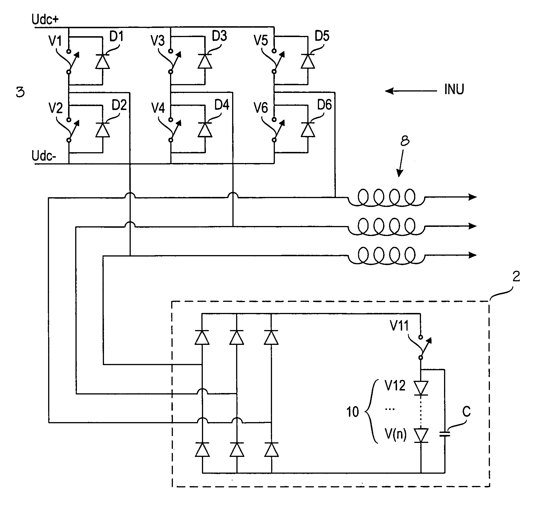
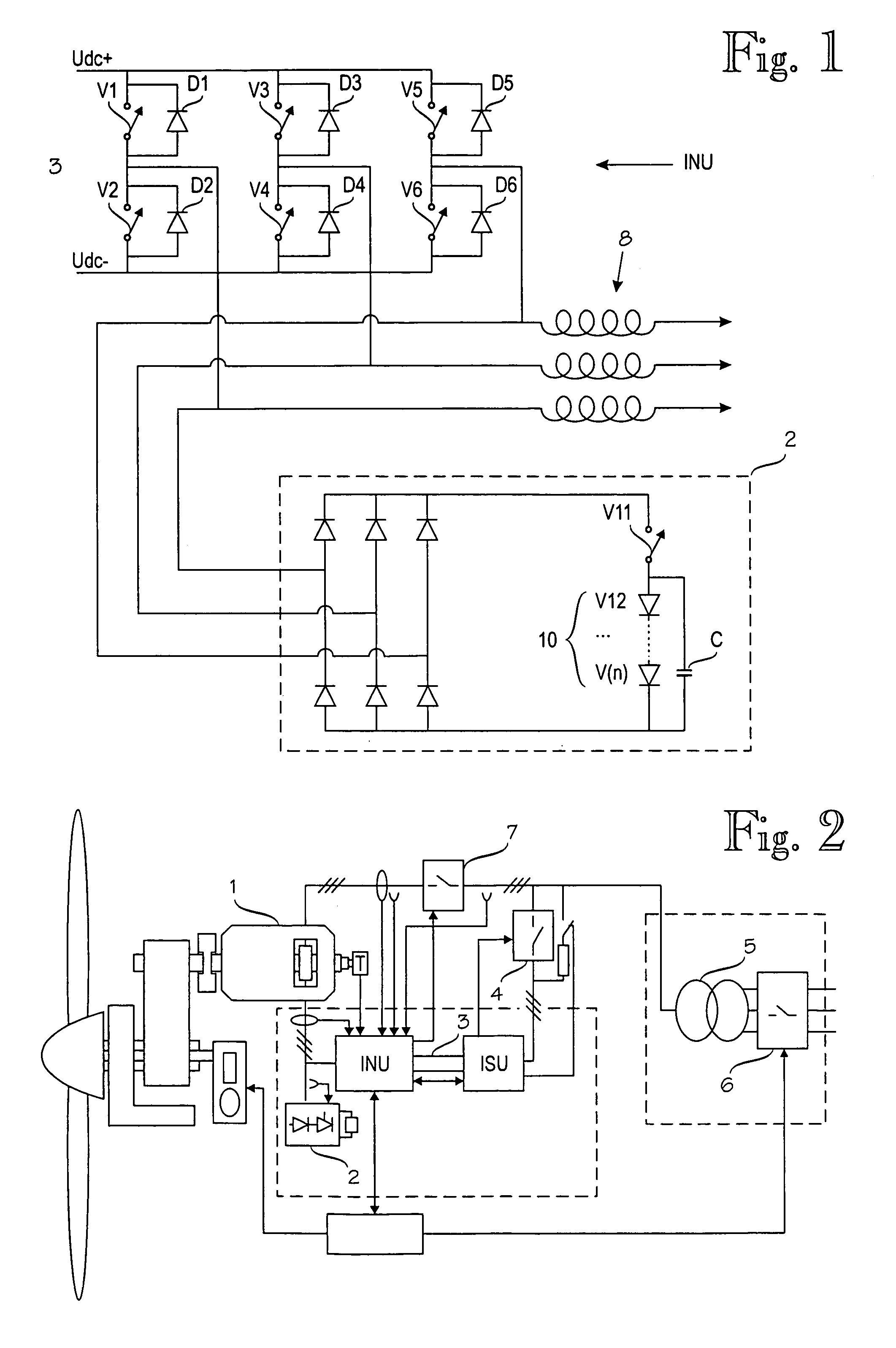
[0015]FIG. 1 shows a protection configuration for a rotor circuit of a double-fed slip-ring generator according to an embodiment of the invention, which protection configuration comprises rotor-side converter means INU, du / dt filters 8 coupled to phases L1 to L3, and a protection circuit 2. For the sake of simplicity, no components configured to measure electrical quantities, to process measurement results and to control switches are shown in the figures.

[0016]The rotor-side converter means INU are provided with a direct voltage side and an alternating voltage side. The direct voltage side is electrically coupled to a direct voltage intermediate circuit 3. The alternating voltage side is electrically coupled to a rotor of a generator. The rotor-side converter means INU comprise means for rectifying the three-phase voltage of the rotor and for feeding it to the direct voltage intermediate circuit 3, as well as means for inverting the direct voltage of the direct voltage intermediate ...


PUM


Abstract

A protection configuration for converter means which comprise a plurality of controllable switches, the protection configuration comprising a protection circuit coupled to the alternating voltage side of the converter means, which protection circuit comprises at least one protective switch configured to short-circuit the alternating voltage side of the converter means, wherein the protection configuration, in predetermined failure situations, is configured to close the protective switch and thus to short-circuit the alternating voltage side of the converter means. After the failure situation has cleared up, the protection configuration is configured to short-circuit the alternating voltage side of the converter means by means of the controllable switches to enhance commutation of the protective switch.

Description

BACKGROUND OF THE INVENTION[0001]The invention relates to protecting converter means of an electric machine drive from overvoltages and overcurrents.[0002]Converters are used in various generator and motor drives. One such electric machine drive comprising converters is a double-fed slip-ring generator configuration whose rotor circuit comprises two converters having a direct voltage intermediate circuit therebetween. One of these converters is situated electrically between the direct voltage intermediate circuit and a rotor while the other converter is situated electrically between the direct voltage intermediate circuit and an electrical network to be supplied.[0003]Such a double-fed slip-ring generator configuration, which has a particular nominal rotational speed, is usually configured to operate within a particular rotation speed range having an upper limit and a lower limit which depend on the selected transformation ratio of a stator and a rotor. The rotational speed range of...

Claims


Application Information

Patent Timeline
Patent Type & Authority Patents(United States)
IPC IPC(8): H02H7/06H02H3/20H02H7/00H02H9/00H02H9/04H02HH02H7/12H02M1/00H02M1/32H02M5/458H02M7/5387H02M7/797H03H7/12
CPCH02M1/32H02P9/10H02P9/007H02M7/5387
Inventor VIRTANEN, REIJO
Owner ABB (SCHWEIZ) AG
Why Eureka
Try Eureka