
Fault isolation in large networks

Active Publication Date: 2007-01-16
ORACLE INT CORP
View PDF14 Cites 114 Cited by
  • Summary
  • Abstract
  • Description
  • Claims
  • Application Information

AI Technical Summary

Benefits of technology

[0008]In one embodiment, a computer accessible medium is contemplated that comprises a plurality of instructions which, when executed, probe nodes in a network to determine if one or more nodes are experiencing any events indicative of a fault. The nodes are probed in a sequence. The instructions, when executed, in response to receiving a first alert transmitted by a first node in the network asynchronous to the probes performed according to the sequence, probe one or more neighbor nodes of the first node. In other embodiments, the instructions, when executed, in response to receiving a first alert transmitted by a first node in the network asynchronous to the probes performed according to the sequence, interrupt probing according to the sequence to probe at least the first node.
[0009]In another embodiment, a computer system comprises a probe agent and an inspector. The probe agent is configured to probe nodes in a network in a s

Problems solved by technology

The devices in a network are prone to faults of various kinds.
Furthermore, a given fault in one device may cause other devices that have some sort of relationship to the device to also experience a fault.
Still further, an environmental event or other factor (e.g. temperature in a room in which a device or devices are located, or power supply to the devices) may cause faults to occur.
Isolating the many faults, correlating the faults, and determine the root cause of the faults is often a complicated task.
However, there may be faults which the device cannot report (e.g. the severity of the fault may prevent the device from communicating, such as the power to the device going off).
However, such approaches do not scale well to large numbers of devices.
For example, if a device experiences a fault soon after being contacted, the fault will not be detected until the next time that device is contacted.

Method used


Image

  • Fault isolation in large networks
  • Fault isolation in large networks
  • Fault isolation in large networks

Examples


Embodiment Construction

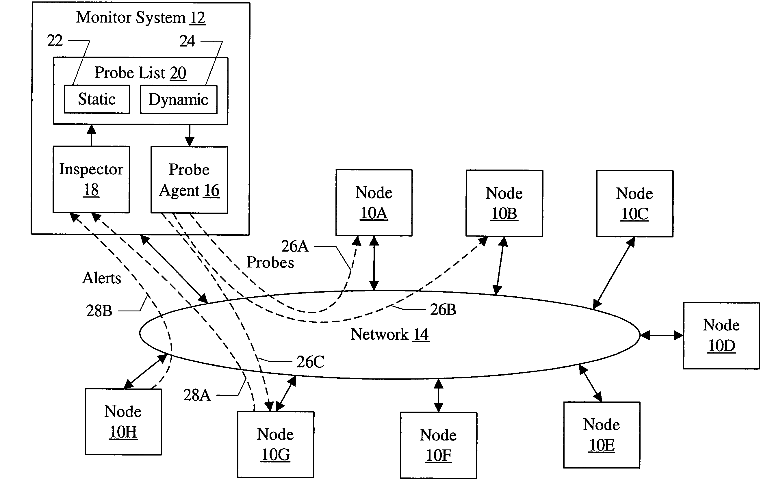
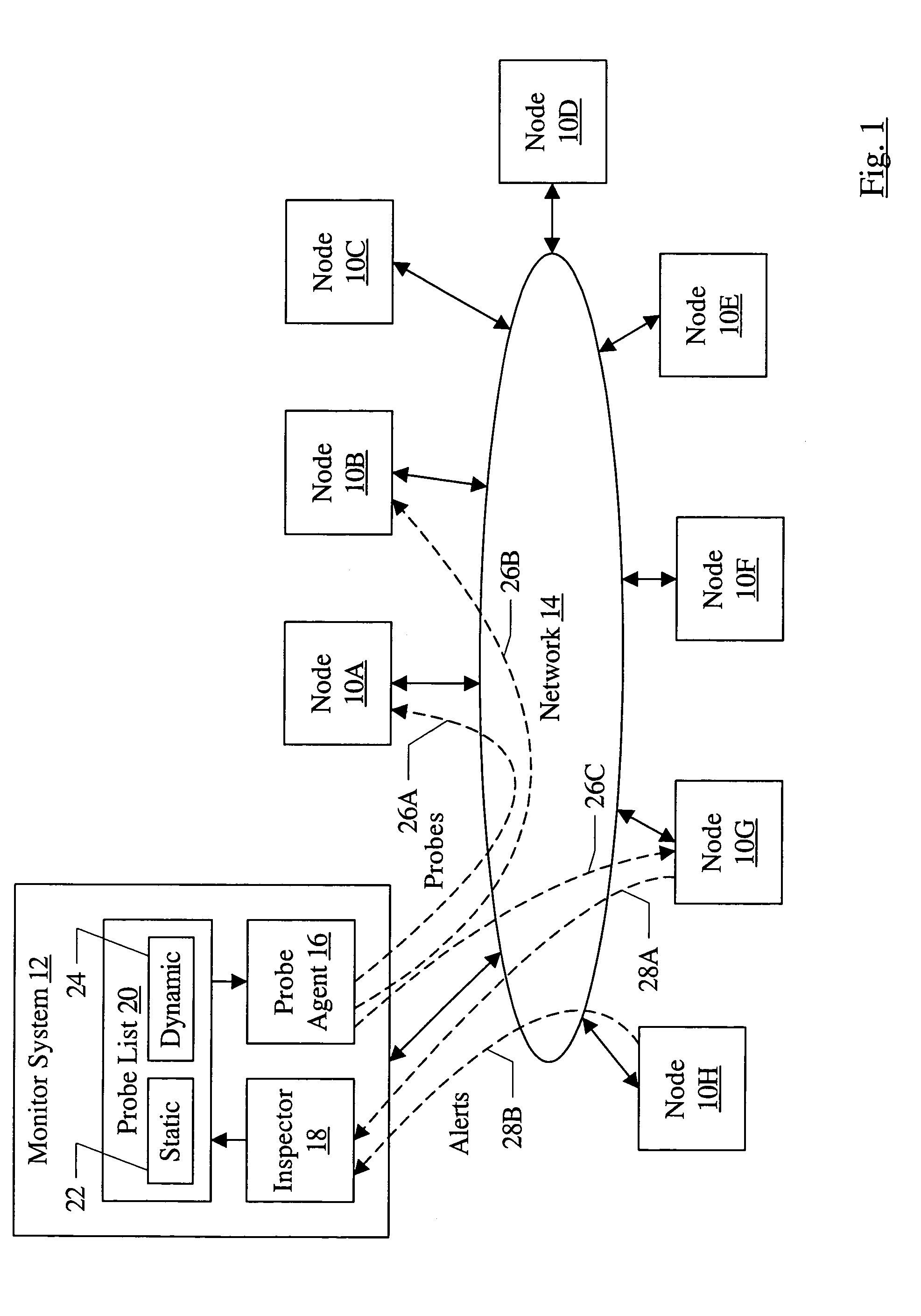
[0020]Turning now to FIG. 1, a block diagram of one embodiment of a networked system including a plurality of nodes 10A–10H, a monitor system 12, and a network 14 is shown. The nodes 10A–10H and the monitor system 12 are coupled to the network 14. In the illustrated embodiment, the monitor system 12 includes a probe agent 16, an inspector 18, and a probe list 20 (which may include, in the illustrated embodiment, a static probe list 22 and a dynamic probe list 24).

[0021]The monitor system 12 may implement a combination of actively probing nodes 10A–10H and receiving alerts from nodes 10A–10H to detect events that may be indicative of a fault. For example, in FIG. 1, probes 26A–26B are illustrated to nodes 10A–10B, and alerts 28A–28B are shown being transmitted by the nodes 10G–10H. As used herein, an “event” may comprise a fault (either a root cause fault or a fault caused by another fault), or any another indication of problematic operation that may subsequently lead to a fault or m...


PUM


Abstract

In some embodiments, a computer accessible medium comprises a plurality of instructions which, when executed, probe nodes in a network to determine if one or more nodes are experiencing any events indicative of a fault. The nodes are probed in a sequence. The instructions, when executed, in response to receiving a first alert transmitted by a first node in the network asynchronous to the probes performed according to the sequence, probe one or more neighbor nodes of the first node. In some other embodiments, the instructions, when executed, in response to receiving a first alert transmitted by a first node in the network asynchronous to the probes performed according to the sequence, interrupt probing according to the sequence to probe at least the first node.

Description

BACKGROUND OF THE INVENTION[0001]1. Field of the Invention[0002]This invention is related to the field of fault isolation in networks of devices.[0003]2. Description of the Related Art[0004]Networks generally connect a set of devices (or nodes). For example, various computer networks (e.g. local area networks (LANs), wide area networks (WANs), metropolitan area networks (WANs), wireless networks, intranets, extranets, the Internet, etc.) connect various computer systems. Storage area networks (SANs) connect various storage devices to a set of hosts.[0005]The devices in a network are prone to faults of various kinds. Furthermore, a given fault in one device may cause other devices that have some sort of relationship to the device to also experience a fault. Still further, an environmental event or other factor (e.g. temperature in a room in which a device or devices are located, or power supply to the devices) may cause faults to occur. Isolating the many faults, correlating the faul...

Claims


Application Information

Patent Timeline
IPC IPC(8): G06F11/00
CPCH04L41/0631H04L43/12H04L41/0677
Inventor CADIEUX, CHRISTIANGIBSON, GAVIN G.
Owner ORACLE INT CORP
Learn More