Motorcycle rear suspension swingarm assembly

a rear suspension and swingarm technology, applied in the field of rear suspension swingarm assemblies, can solve the problems increasing and the arrangement cannot be easily achieved for a reasonable cost, so as to improve the strength and stiffness of the arm, increase and increase the weight of the swingarm assembly. the effect of increasing the size of the arm

Inactive Publication Date: 2007-01-23
YAMAHA MOTOR CO LTD
View PDF30 Cites 6 Cited by
  • Summary
  • Abstract
  • Description
  • Claims
  • Application Information

AI Technical Summary

Benefits of technology

[0010]To achieve such an arrangement, the arm(s) are often slightly bent at an intermediate location, or region, between the forward and rearward ends. This bending step may be a part of the swaging process or it may be a separate process step. In either situation, the bending of the arm causes the inner wall of the arm within the intermediate region, i.e., where the arm is bent, to deform and assume a concave shape. That is, the intermediate region of the inner wall collapses inward, toward the outer wall of the arm. The convex shape of the inner wall within the intermediate region of the arm compromises the strength and stiffness of the arm and, as a result, the dimensions of the arm are increased to compensate for the compromised condition. Increasing the size of the arm undesirably increases the weight of the swingarm assembly.

Problems solved by technology

Increasing the size of the arm undesirably increases the weight of the swingarm assembly.
However, as described above, such an arrangement cannot be easily achieved for a reasonable cost with current manufacturing methods.

Method used


Image

  • Motorcycle rear suspension swingarm assembly
  • Motorcycle rear suspension swingarm assembly
  • Motorcycle rear suspension swingarm assembly

Examples


Embodiment Construction

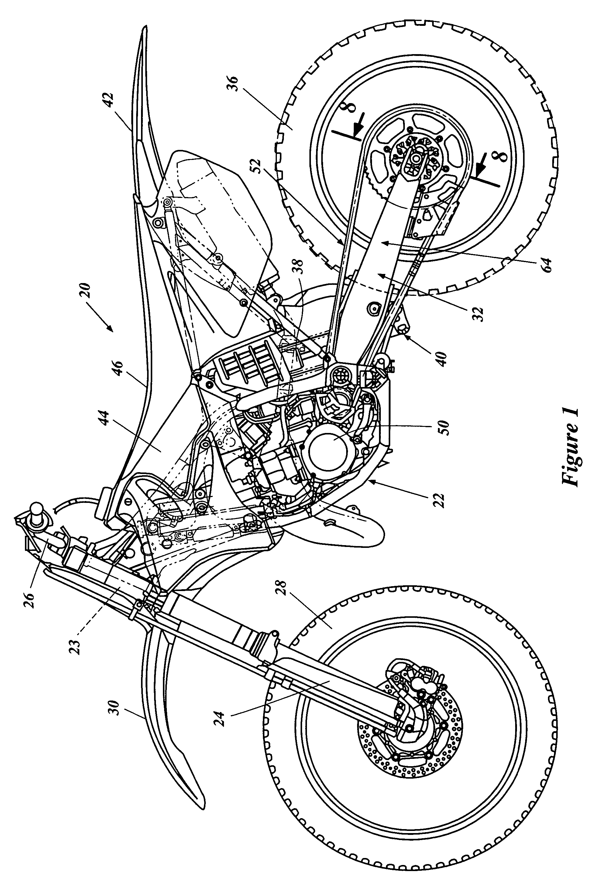
[0031]With reference to FIG. 1, an off-road motorcycle incorporating a preferred rear suspension swingarm assembly is identified generally by the reference numeral 20. The motorcycle 20 includes a frame assembly 22 that is formed primarily from tubular members, which may have circular or other suitable cross-sectional configurations.

[0032]The frame assembly includes a head pipe 23. A front suspension fork assembly 24 is journaled for rotation with respect to the frame assembly 22. In particular, the front suspension fork assembly extends through the head pipe 23 of the frame assembly 22. A handlebar assembly 26 is carried at an upper end of the front fork assembly 24 and can be used to steer a front wheel 28, which is rotatably journaled at a lower end of the fork assembly 24 in any suitable manner. The front fork assembly 24 also supports a front fender 30 at a position above the front wheel 28. The front fender 30 is arranged to deflect dirt, mud or other debris that may be thrown...


PUM

PropertyMeasurementUnit
weight ratioaaaaaaaaaa
sizeaaaaaaaaaa
rectangular shapeaaaaaaaaaa

Abstract

An off-road motorcycle incorporates a swingarm assembly for pivotally supporting a rear wheel relative to a frame of the motorcycle. Preferably, the swingarm includes right and left arms extending rearwardly from a forward connecting portion. Right and left rear wheel mount members are secured to the right and left arms, respectively, to rotatably support the rear wheel of the motorcycle. Preferably, the arms of the swingarm assembly are formed at least partially by a hydroforming process and the center of each of the arms has a width that is greater than the width of either a forward or rearward end of the arm. In addition, the forward end of each of the right end left arms preferably is bent inward such that the forward portion of the swingarm assembly is narrower than the rear portion of the swingarm assembly. The hydroforming process permits the inner wall of the arms to be vertical and substantially planar along the region where the arms are bent about a generally vertically extending axis. In addition, a vibration absorbing coating can be applied to the wheel support members in a manner to be interposed between an inner surface of the wheel support members and the outermost portion of a hub of the rear wheel.

Description

PRIORITY INFORMATION [0001]This application is a division of U.S. application Ser. No. 10 / 178,622, filed on Jun. 20, 2002 now abandoned, the entirety of which is incorporated by reference herein, which application was related to, and claimed priority from, Japanese Patent Application No. 2001-185806, filed on Jun. 20, 2001, the entirety of which also is incorporated by reference herein.BACKGROUND OF THE INVENTION [0002]1. Field of the Invention[0003]This invention relates generally to vehicle suspension systems. More particularly, this invention relates to a rear suspension swingarm assembly for supporting a rear wheel of a motorcycle.[0004]2. Description of the Related Art[0005]Motorcycles generally include an engine supported within a cradle-type frame assembly. A typical arrangement includes front suspension fork assembly supported by the frame for rotation about a steering axis and supporting a front wheel of the motorcycle at its lower end. A handlebar assembly is mounted to th...

Claims


Application Information

Patent Timeline
Patent Type & Authority Patents(United States)
IPC IPC(8): B23P17/00B62K11/02B62K19/06B62K25/28
CPCB62K25/283Y10T29/4998Y10T29/49805
Inventor MIYASHIRO, SHIDEHIKO
Owner YAMAHA MOTOR CO LTD
Why Eureka
Try Eureka