

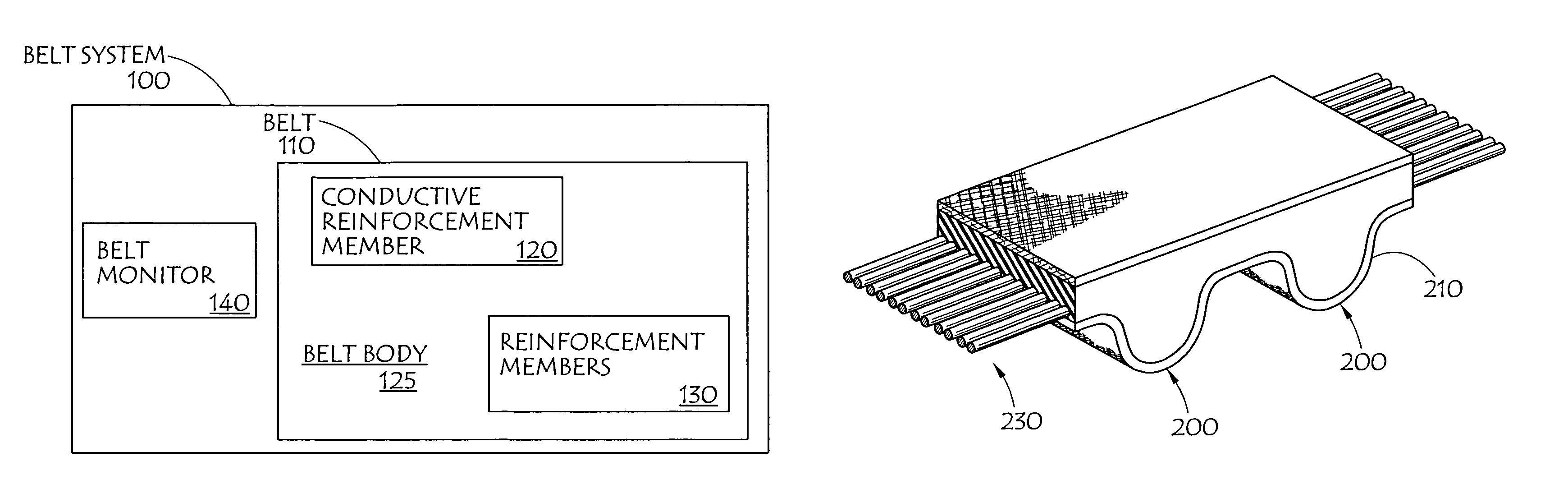
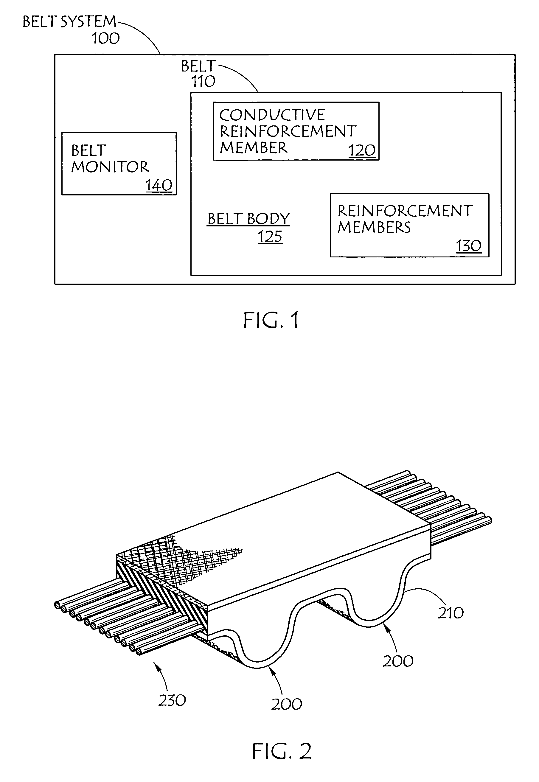
Belt monitoring systems and methods
a belt and monitoring system technology, applied in the field of belt monitoring systems and methods, can solve the problems of high cost and special production methods for embedding such sensors, and achieve the effect of compromising the robustness, integrity and strength of the bel
- Summary
- Abstract
- Description
- Claims
- Application Information
AI Technical Summary
Benefits of technology
Problems solved by technology
Method used
Image

Examples
embodiment 500
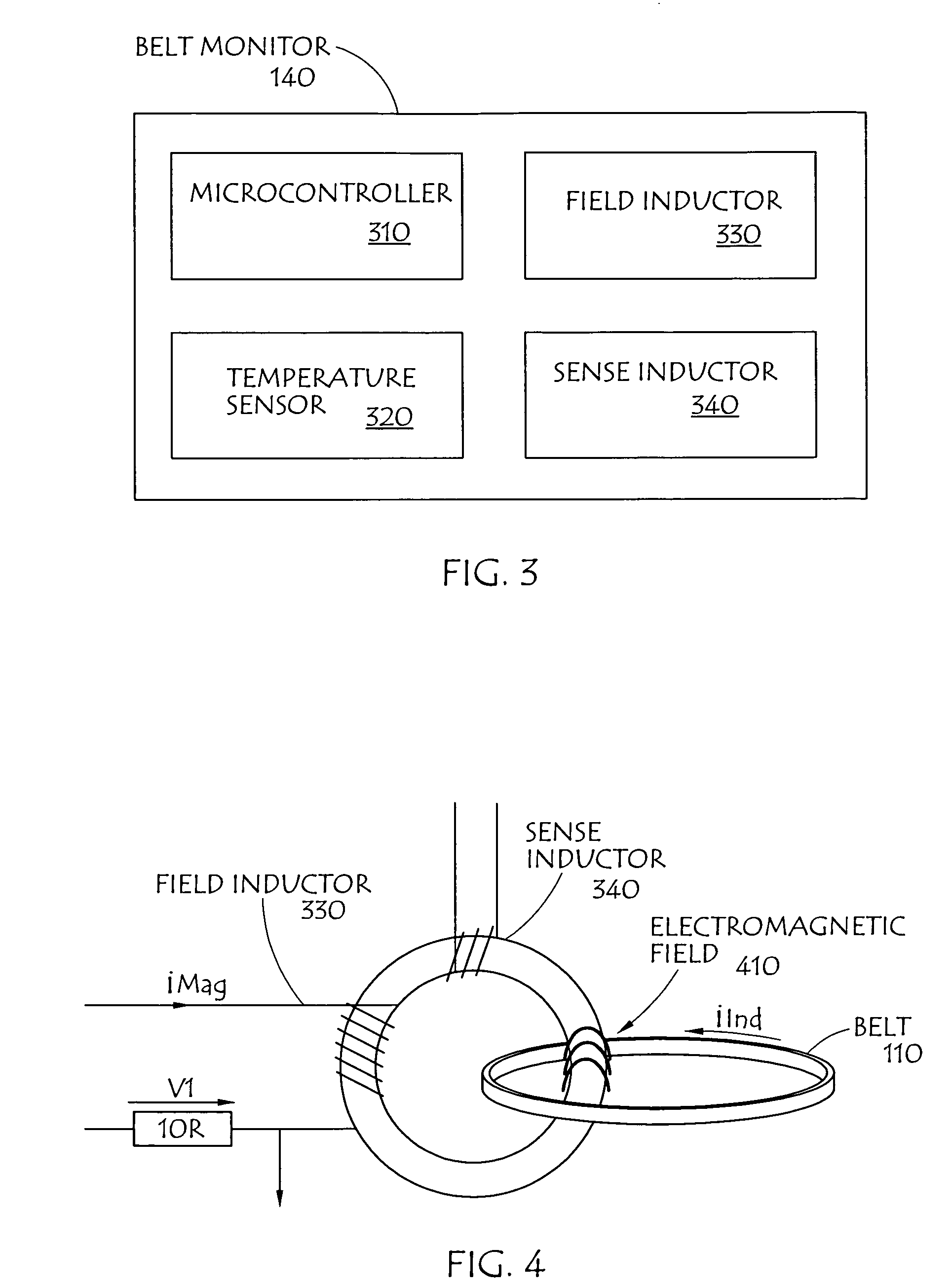
[0025]In operation, field inductor 330 may be excited by an applied signal, such as a voltage signal, at 520 of FIG. 5 which is a flowchart of embodiment 500 of a method for detecting belt condition. This signal may be employed at a terminal of field inductor 330 and may be a bipolar signal such as for example alternating current voltage waveform signal, varying direct current waveform signal or the like. The application of a voltage will preferably result in the generation of electromagnetic field 410 by field inductor 330.
[0026]A transformer may comprise a primary and secondary winding. Typically such a transformer exhibits a phase difference between the voltage and current signals of the primary and secondary winding approaching ninety degrees where the secondary winding has impedance approaching infinity, known as an open turn winding. Alternatively, when the impedance of the secondary winding approaches zero, the aforementioned phase difference also approaches zero degrees. In ...
embodiment 700
[0032]FIG. 7 is a flowchart of embodiment 700 of a temperature adjustment process that may be employed in DSP process 600, at step 650. At 710 an environmental temperature is measured. At 715 a polynomial temperature compensation equation is applied to the measured temperature. The equation result produced at 720 is subtracted from raw acquisition data from 740 at 730. The compensated data resulting at 750 may be supplied to DSP process 600 for use at 650.
[0033]FIG. 8 is a flowchart of an embodiment of calibration / data acquisition process 800 that may be employed on the data used in DSP flow 600 in FIG. 6. At 810 a sweep frequency is set. At 820 time may be allotted to allow stabilization of the core of field inductor 330. Data acquisition is initialized at 830. At 840 a determination is made at 840 as to whether the data acquisition is complete, if not a wait state is initiated. If the data acquisition is complete at 840, temperature compensation 700 is carried out at step 850. At ...
embodiment 900
[0034]FIG. 9 is a flowchart of embodiment 900 of an extraction algorithm that may be employed as a part of Data acquisition and calibration process 800. At 920 a difference array showing, for example the rate of change between the calibration data and any subsequently acquired data is constructed at 920. The difference array, any calibration or subsequently acquired data may include information relating to frequency, amplitude, waveform symmetry of the signal and / or the like. For example, at 920 a newly acquired array element X may be subtracted from a calibrated X element and the result may be stored as difference X. Then at 930 array element X may be incremented. Once it is determined at 940 that subtraction of elements in 920 is complete. Data may be extracted from the difference array and the difference array may be modified. For example, the contents may be squared at 950 in such a manner as to provide squared modulus data. Such data may advantageously increase perceived magnit...
PUM
 Abstract
Description
Claims
Application Information