Automated ball valve and actuator

a technology of actuators and ball valves, applied in the direction of valve arrangements, plug valves, mechanical equipment, etc., can solve the problems of affecting the performance of the valve, the reaction torque is significant, and the production and operation characteristics of ball valves and actuators are not optimized in the standard to achieve the effect of increasing the ability of the stem seal

Inactive Publication Date: 2012-07-03
GEMINI VALVE
View PDF5 Cites 12 Cited by
  • Summary
  • Abstract
  • Description
  • Claims
  • Application Information

AI Technical Summary

Benefits of technology

[0007]The present invention obviates the short comings and disadvantages of the described prior structures and arrangements. In particular, one aspect of the present invention is directed to an improved valve stem seal which significantly increases the ability of the stem seal to resist leakage over its lifetime and the number of cycles applied to the valve by the actuator.
[0008]Another aspect of the invention provides a secure and integral connection between the ball valve body and the actuator body so that the torque and shear forces applied between the actuator and the ball valve body during operation do not allow for relative motion between the two elements and thereby prevent misalignment of the stem shaft with the actuator pinion that would otherwise compromise the stem seal.
[0010]It is yet another object of the present invention to provide a maintenance free ball valve stem seal that does not use a threaded packing nut that can come loose or fail during the course of the operative lifetime and a high number of cycles of the ball valve. By eliminating the threaded packing nut there is no chance or risk of improper manual adjustment either during assembly, installation or maintenance.
[0011]It is another still further object of the present invention to significantly reduce the shear and torque forces between the actuator and ball valve body which correspondingly loosen the connection therebetween and compromise the integrity of the connection between the actuator and the ball valve stem and thus the accurate actuation of the ball valve by the actuator.
[0012]The present invention utilizes a compression spring in combination with an external O-ring to reduce the amount of friction wear as well as to compensate for any wear of the external O-ring resulting from cycling of the ball valve. Also, the present invention includes a precise, dimensionally controlled mounting device for ensuring that the ball valve body is accurately and securely affixed to the actuator body in a manner which reduces the torque and sheer forces between these two elements. The reduction of such detrimental forces ensures that the centrality of the actuator pinion and valve stem is maintained so as to provide a highly accurate actuation of the ball valve via the actuator throughout a significantly increased lifetime of the valve and actuator.

Problems solved by technology

These standards ensure that there is some consistency across the industry, however the standards do not optimize the manufacturing and operating characteristics necessary to produce ball valves and actuators with a long lifespan.
These bolts are generally aligned in parallel with the valve stem and are subject to a significant amount of reaction torque and shear stress that occurs between the actuator and valve from internal seals and packings as well as the additive effects of forces created by fluid dynamics acting on the ball valve.
Also, the axial length of the bonnet and the valve stem of the known ball valves defines a substantial distance between the actuator and the ball valve which can accentuate the torque and shear forces and so apply tremendous stress on these bolts over time.
Even before failure, any loosening of the standard valve and actuator connection due to such torque and shear forces causes misalignment between the valve stem and the rotation axis of the actuator.
At the very least such a loss of centrality, or axial misalignment between the rotation axis of the valve stem and that of the actuator can place significant pressure and force on the valve seal accelerating wear and causing external leaks.
In the worst case scenario, the valve stem seals can fail altogether and / or the valve body separates from the actuator.
These conventional type of connections between the valve body and the actuator can survive only a certain number of cycles before failure or maintenance which of course affects not only the efficiencies and costs relating to the ball valve and actuator but which shuts down the entire process in which these devices are used.

Method used


Image

  • Automated ball valve and actuator
  • Automated ball valve and actuator
  • Automated ball valve and actuator

Examples


Embodiment Construction

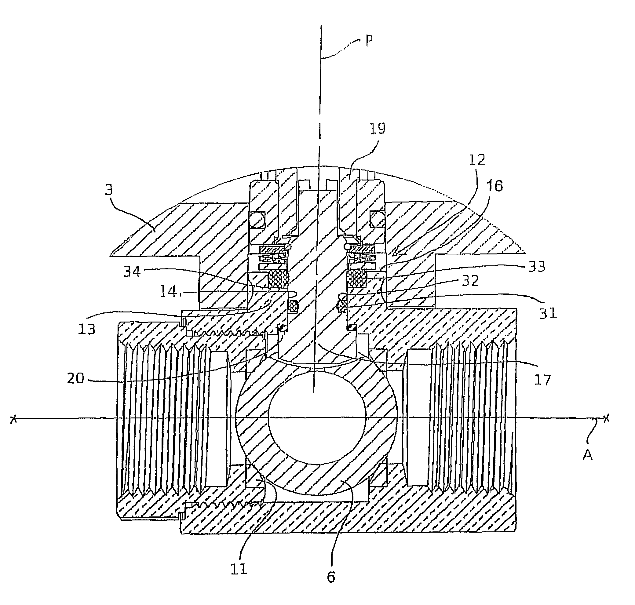
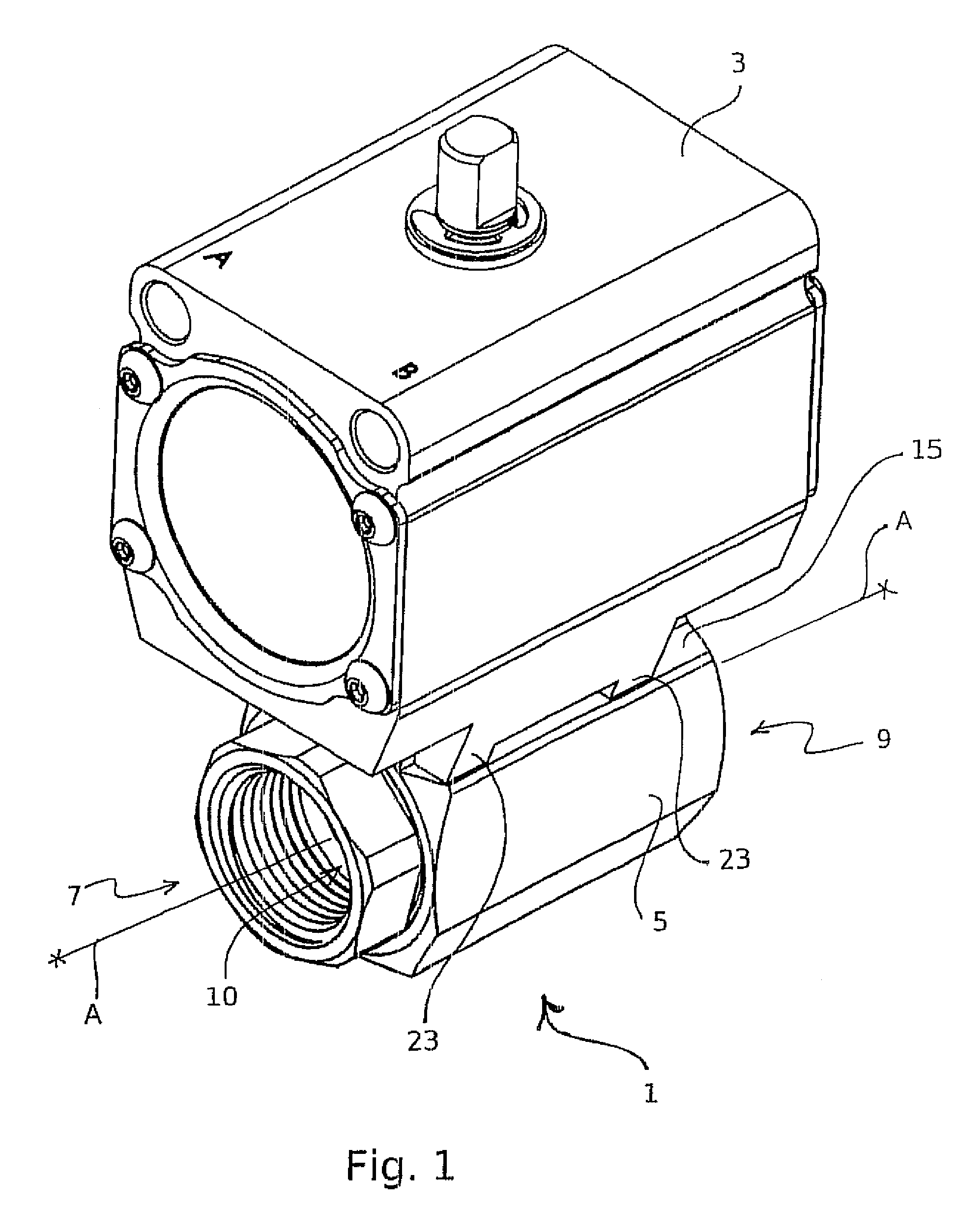
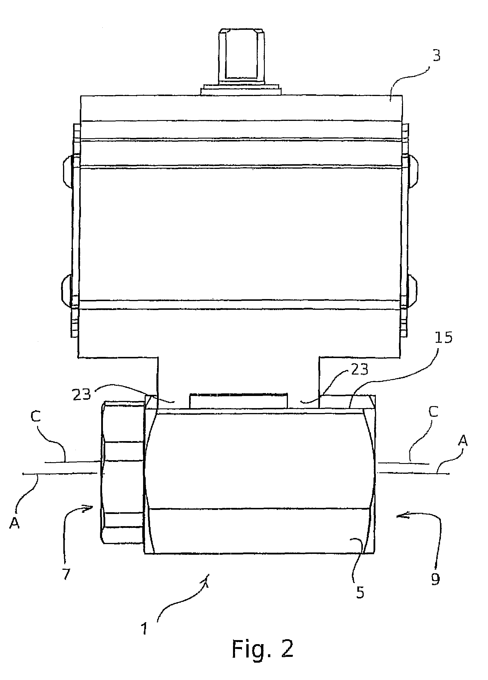
[0026]Initially observing FIGS. 1-3 the present invention is embodied in a ball valve 1 connected to a ball valve actuator 3. The ball valve 1 is contained by a valve body 5 having an inlet 7 and an outlet 9 at opposing ends of the valve body 5 which define a passageway 10 therebetween along an axis A. As is well known, during use a fluid passes through the passageway 10 from the inlet 7 to the outlet 9 and the fluid flow is controlled by the orientation of the ball 6 inside the ball valve 1 which moves between an open position and a closed position to control the fluid flow through the passageway 10. The inner surface of the inlet 7 and outlet 9 is generally provided with a threaded connection in order to connect to the threads on an external surface of a pipe (not shown) connected to the inlet 7 and to the outlet 9 at either side of the valve body 5. As the general structure and operation of such ball valves 1 and fittings are well known in the art, no further discussion is provid...


PUM


Abstract

A ball valve and ball valve actuator including a unique valve stem seal and mounting connection between the ball valve and actuator. The stem seal design reduces leakage issues and significantly lengthens the life span of the ball valve and actuator and the mounting connection between the actuator. The ball valve maintains the centrality of the valve stem in connection with the actuator pinion and minimizes torque and shear forces transferred to the valve stem and hence the stem seal itself.

Description

FIELD OF THE INVENTION[0001]The present invention relates to a ball valve and ball valve actuator and more specifically to a unique valve stem seal and mounting connection between the ball valve and actuator. The stem seal design reduces leakage issues and significantly lengthens the life span of the ball valve and actuator and the mounting connection between the actuator. The ball valve maintains the centrality of the valve stem in connection with the actuator pinion and minimizes torque and shear forces transferred to the valve stem and hence the stem seal itself permitting use of smaller electric actuators then known conventionally to operate the ball valve.BACKGROUND OF THE INVENTION[0002]Many industrial processes include liquid, semi-liquid and gas distribution systems which require automation of ball valves in the distribution pipelines of the industrial processes. Examples of such processes are food processing, chemical manufacturing and PET blow molding operations. In such p...

Claims


Application Information

Patent Timeline
Patent Type & Authority Patents(United States)
IPC IPC(8): F16K5/00
CPCF16K5/0647F16K5/0694
Inventor MADDEN, KENNETHHARRIS, DANIEL
Owner GEMINI VALVE
Why Eureka
Try Eureka