Shaft structure for cooling fan rotor

a technology of shaft structure and cooling fan, which is applied in the direction of machines/engines, mechanical equipment, liquid fuel engines, etc., can solve the problems of insufficient firmness of the combination, the difficulty of applying this art in manufacturing the ceramic fan shaft, and the comparatively shorter useful life of the fan using this prior art, so as to prolong the useful life of the cooling fan. the effect of inferior engagemen

Inactive Publication Date: 2007-01-23
ACT RX TECH CORP
View PDF1 Cites 16 Cited by
  • Summary
  • Abstract
  • Description
  • Claims
  • Application Information

AI Technical Summary

Benefits of technology

[0004]The present invention provides a shaft structure which is not only able to firmly combine one end of the fan shaft with the fan blade but also suitable for a ceramic fan shaft manufacturing. It resolves the longstanding problems like difficulty to manufacture the ceramic fan shaft, inferior engagement between the fan shaft and the fan blade, and other drawbacks. It successfully extends the useful lifetime of the cooling fan.
[0005]The shaft structure provided by the present invention includes an annular groove portion, an end head adjacent to the groove portion, and several teeth equally cut from the surface of the shaft. The present invention enables the center part of the fan blade to enwrap the insert part of the fan shaft, and firmly engage with the fan shaft. It is, therefore, not only able to enhance the robustness of the combination but also successful in preserving the adhesion effect between the fan shaft and the fan blade.

Problems solved by technology

It is pretty difficult to apply this art in manufacturing the ceramic fan shaft.
Moreover, because the twill of the knurl 102a is shallow, the combination is not firm enough and therefore quite probable to separate.
Consequently, the useful lifetime of the fan using this prior art is comparatively shorter.

Method used


Image

  • Shaft structure for cooling fan rotor
  • Shaft structure for cooling fan rotor
  • Shaft structure for cooling fan rotor

Examples


first embodiment

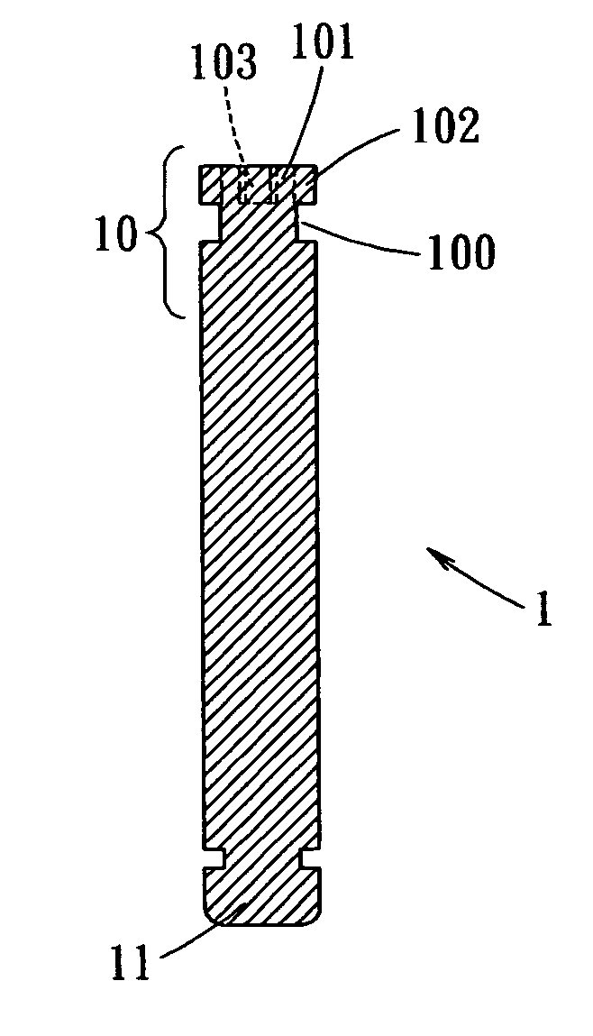
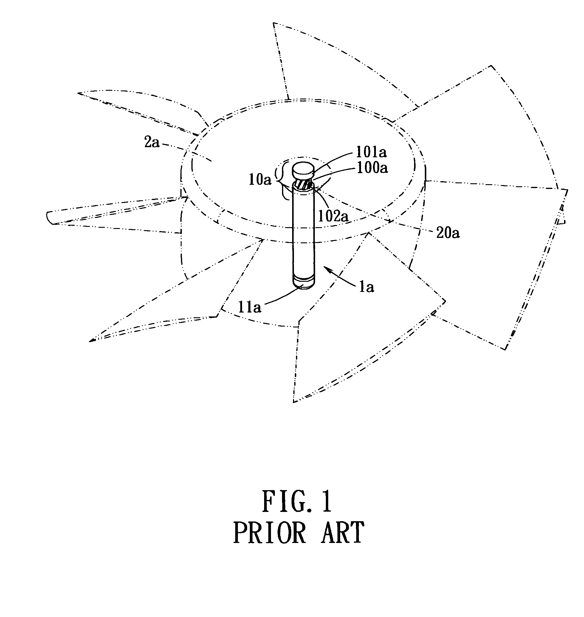
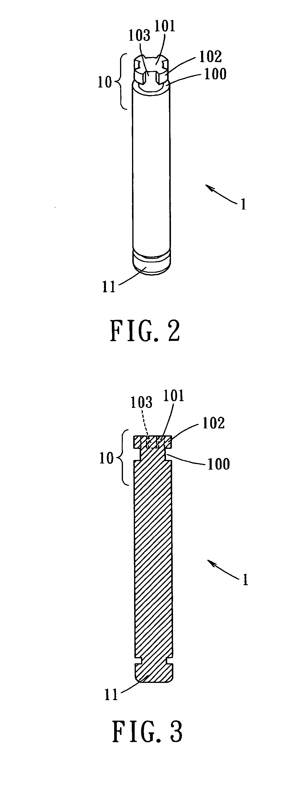
[0020]Referring to FIG. 2 through 4, a perspective view, an axial cross-sectional view, and a vertical cross-sectional view (after insert molding) of a fan shaft in accordance with the present invention are shown. The fan shaft 1 has a longitudinal rod shape, with one upper end portion 10 and one lower end portion 11. The lower end portion 11 is a free end portion. The other end portion 10 is assembled into the center part 20 of the fan blade 2, as illustrated in FIG. 4. By means of the fan shaft 1, the fan blade 2 is installed onto a fan stator, which is not shown in the figure, spins around the fan shaft 1 and produces airflow.

[0021]Because the end portion 10 of the fan shaft 1 is utilized together with the fan blade 2 for insert molding, it can be defined as an “insert part.” The insert part 10 includes an annular groove portion 100 cut around close to the top of the fan shaft 1, an end head 101 adjacent to the annular groove portion 100, and several teeth 102 equally cut from th...

second embodiment

[0023]Referring to FIG. 5 and FIG. 6, a perspective view, and an axial cross-sectional view of a fan shaft in accordance with the present invention are shown. The teeth 102 are equally spaced on the surface of the annular groove portion 100. The shape of the end head 101 is preserved completely.

third embodiment

[0024]Referring to FIG. 7 and FIG. 8, a perspective view and a radial cross-sectional view of a fan shaft in accordance with the present invention are shown. The end head 101 and the annular groove portion 100 are the same. In addition, the teeth 102 are cut from the circumference of the fan shaft 1 below and close to the annular groove portion 100. The gaps 103 are therefore produced between each pair of the teeth. Because the outside diameter of the gear formed by the teeth 102 is the same as the diameter of the fan shaft 1, the top lands of the teeth 102 are aligned with the circumference of the fan shaft 1.

[0025]Referring to FIG. 9 and FIG. 10, a perspective view, and an axial cross-sectional view of a fan shaft in accordance with the fourth embodiment of the present invention are shown. This embodiment is derived from the third embodiment of the present invention. Wherein, each gap 103 extends toward the annular groove portion 100 and links together with it.

[0026]Consequently, ...


PUM


Abstract

A fan shaft structure includes an annular groove portion, an end head adjacent to the groove portion, and several teeth equally spaced around the surface of the shaft. The annular groove portion, end head and teeth constitute an insert part of the fan shaft, around which the plastic fan blade is molded by insert molding. The present invention enables the center part of the fan blade to enwrap the insert part of the shaft, and firmly engage with the shaft. It is, therefore, not only able to enhance the robustness of the combination but also successful in preserving the adhesion effect between the shaft and the fan blade.

Description

BACKGROUND OF THE INVENTION[0001]The present invention relates in general to a fan shaft structure, and more particular, to a fan shaft structure suitable for a ceramic fan shaft, which is provided for combining firmly the fan shaft with the fan blade and preventing the combination from separation caused by long-term utilization.[0002]Referring to FIG. 1, a perspective view of a conventional fan rotor in accordance with the prior art is shown. The fan shaft 1a has a longitudinal rod shape, with one upper end portion 10a and one lower end portion 11a. The lower end portion 11a is a free end portion. The other end portion 10a is assembled into the center part 20a of the fan blade 2a. The end portion 10a includes an annular groove portion 100a, and an end head 101a adjacent to the groove portion 100a. There are knurls 102a by roller forming on the root surface of the annular groove portion 100a. When utilizing this shaft structure to fabricate the fan rotor by insert molding, because t...

Claims


Application Information

Patent Timeline
Patent Type & Authority Patents(United States)
IPC IPC(8): F04D29/04F04D29/056F04D29/057F04D29/26
CPCF04D29/0566F04D29/263F04D29/057
Inventor CHEN, WEI-MINGCHENG, CHIH-MINGCHOU, CHEN-LUNGLIU, KUANG-HSIN
Owner ACT RX TECH CORP
Why Eureka
Try Eureka