Printing system and method

a printing system and printing method technology, applied in the field of printing systems, can solve the problems of inability to perform multi-stage conversion processing for converting print data into intermediate format once and further converting it into the final format in this manner

Active Publication Date: 2007-01-23
FUJIFILM BUSINESS INNOVATION CORP
View PDF5 Cites 12 Cited by
  • Summary
  • Abstract
  • Description
  • Claims
  • Application Information

AI Technical Summary

Problems solved by technology

Also, it is necessary to acquire the print data from the data server device and to perform conversion processing, so that a processing load of the client device is large and during these processing, many machine powers can be spent in other processing.
Also, as a matter of course, the print data cannot be printed unless an application is provided in the printer.
However, in the single stage conversion method shown in FIG. 3, all the conversion processing of the print data read from the data server device must be processed and printed by one processor, so that conversion processing which is not provided in the processor cannot be performed as a matter of course.
However, according to the single stage conversion method shown in FIG. 3, multistage conversion processing for converting the print data into the intermediate format once and further converting it into the f

Method used


Image

  • Printing system and method
  • Printing system and method
  • Printing system and method

Examples


first embodiment

[0100]A first embodiment of the invention will be described below.

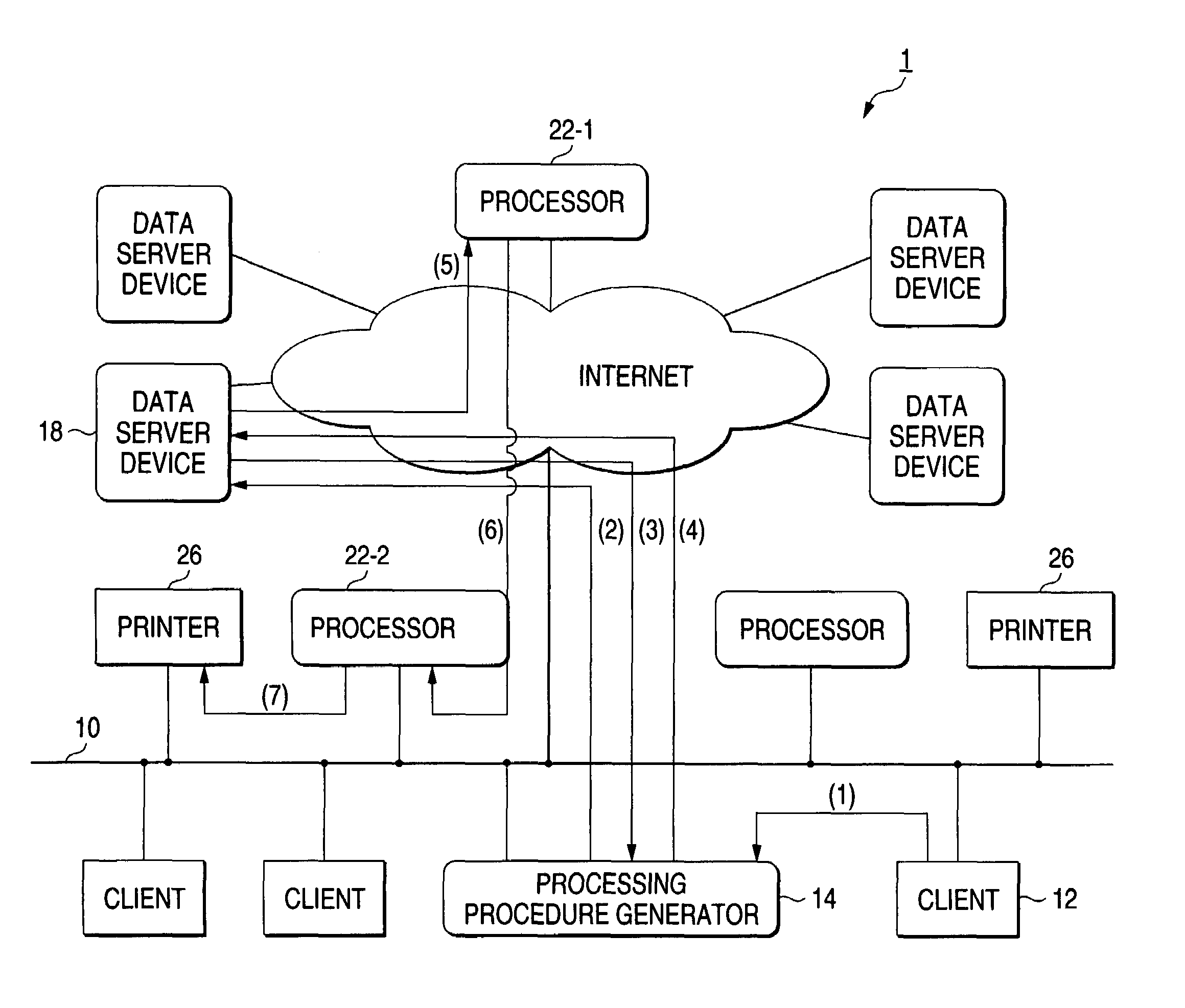
[0101]FIG. 6 is a diagram showing a configuration of a first printing system 1 according to the invention.

[0102]As shown in FIG. 6, the printing system 1 is constructed by connecting client devices 12, a processing procedure generator 14, data server devices 18, n units of processors 22 and printers 26 through a network 10.

[Client Device 12]

[0103]FIG. 7 is a diagram showing a hardware configuration of the client devices 12, the processing procedure generator 14, the data server devices 18 and the processors 22 (hereinafter merely called “processors 22” in the case of showing any of processors 22-1 to 22-n without identification) shown in FIG. 6.

[0104]As shown in FIG. 7, the client device 12 comprises a body 100 including a CPU 102 and memory 104, a display device 110 such as a CRT display, an input device 112 such as a keyboard and a mouse, a communication device 114 for conducting communication with the network 10, a...

second embodiment

[0193]A second embodiment of the invention will be described below.

[0194]FIG. 18 is a diagram showing a configuration of a second printing system 1′ according to the invention.

[0195]In FIG. 18, like reference characters are designated to those similar to the components of the client device 12 etc. shown in FIG. 6.

[Processing Procedure Generator 14]

[0196]A processing procedure generator 14 performs similar operations in the printing system 1 shown in FIG. 6.

[0197]Based on the determination, the processing procedure generator 14 further generates processing procedure data including an address for specifying a device to perform processing, a command for specifying processing to be performed by a device, a name indicated by print data to be printed and answer information into which a result of processing is written every device in order of processing as illustrated in FIG. 8.

[0198]In an example shown in FIG. 18, processing procedure data is generated in the processing procedure generato...

third embodiment

[0213]A third embodiment of the invention will be described below.

[0214]FIG. 20 is a diagram showing a configuration of a third printing system 1″ according to the invention.

[0215]In FIG. 20, like reference characters are designated to those similar to the components of the client device 12 etc. shown in FIG. 6.

[Processing Procedure Generator 14]

[0216]A processing procedure generator 14 performs similar operations in the printing system 1 shown in FIG. 6.

[0217]Based on the determination, the processing procedure generator 14 further generates processing procedure data including an address for specifying a device to perform processing, a command for specifying processing to be performed by a device, a name indicated by print data to be printed and answer information into which a result of processing is written every device in order of processing as illustrated in FIG. 8.

[0218]In an example shown in FIG. 20, processing procedure data is generated in the processing procedure generator ...


PUM


Abstract

When a client device issues a print request, a processing procedure generator outputs processing procedure data indicating a procedure of processing to a device that acquires the print data indicated by the processing procedure data, and sends the print data along with the processing procedure data to a processor. The processor performs N-up etc. indicated by a command of the processing procedure data with respect to the print data body and further, a processor performs format conversion with respect to the print data body, and performs sending to a printer. The printer prints the processed print data.

Description

BACKGROUND OF THE INVENTION[0001]1. Field of the Invention[0002]The present invention relates to a printing system for requesting processing and printing with respect to a processor and a printer, which are connected to each other through a network to make the processor and the printer perform processing and printing of data to be printed and a method therefor.[0003]2. Description of the Related Art[0004]When print data is acquired from a data server device connected to a network and is printed, a place of the print data, a printer of a print destination and an application capable of converting the print data into a format suitable for the printer are required.[0005]That is, as the necessary minimum number of configurations for printing, a client device for issuing a print request of print data by an operation of a user, a data server device for holding the print data, a printer for doing printing and further the application for making the conversion described above are required.[00...

Claims


Application Information

Patent Timeline
IPC IPC(8): G06F3/12G06F15/00
CPCG06F3/1288G06F3/1212G06F3/1247G06F3/124G06F3/122
Inventor MURAMOTO, MICHIKOYOSHIMURA, KOICHI
Owner FUJIFILM BUSINESS INNOVATION CORP
Why Eureka
Try Eureka