External tube deforming extraction device

a tube and extraction device technology, applied in metal-working equipment, metal-working equipment, manufacturing tools, etc., can solve problems such as tube stub section, cutting torch use errors, and damage to the drum and the opening, and achieve the effect of facilitating the removal of tubes, and facilitating the use of devices

Inactive Publication Date: 2007-01-30
BABCOCK & WILCOX CANADA LIMITED
View PDF43 Cites 2 Cited by
  • Summary
  • Abstract
  • Description
  • Claims
  • Application Information

AI Technical Summary

Benefits of technology

[0015]It is a further object of the invention to provide a simplified device for facilitating the removal of tubes from a drum or tube sheet without damaging the tube sheet bonding surfaces.
[0016]Accordingly, an object of the invention is to provide a tube extraction device which facilitates the removal of a tube from a tube hole in a drum. The device comprises a housing which is mounted over an exterior surface of the drum. The housing has an opening which receives a part of the tube. The device has a wedge which is slidably mounted in the housing. The wedge has a slanted face and a bottom edge. A thrusting ram is slidably mounted in the housing. The side thrusting ram laterally moves the wedge so that the slanted face indents the tube inwardly. A drive down ram is slidably mounted in the housing. The drive down ram drives the wedge down into the zone between the tube outside wall and the tube hole so that the tube collapses into the tubes hole.
[0017]It will be seen that use of the device is very rapid and removal of a tube from its secured connection in the boiler drum opening is materially facilitated, thereby materially reducing the costs involved in retubing a boiler or replacing a tube. The tool is light and portable enough so that a single workman utilizing the tool can readily and rapidly accomplish the job of removing the boiler tubes from a boiler. In the past, such a retubing operation normally required several workmen.

Problems solved by technology

These methods have often resulted in damage to the drum and the opening through which the tube stub section projected.
Errors in use of the cutting torch can, of course, damage the tube sheet requiring expensive refinishing and repair work.

Method used


Image

  • External tube deforming extraction device
  • External tube deforming extraction device
  • External tube deforming extraction device

Examples


Embodiment Construction

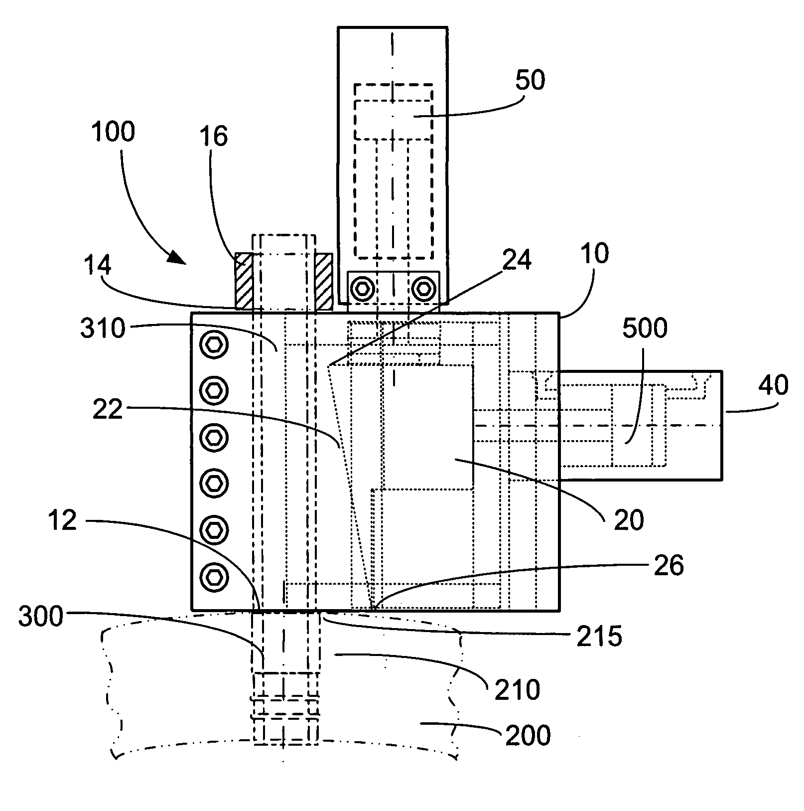
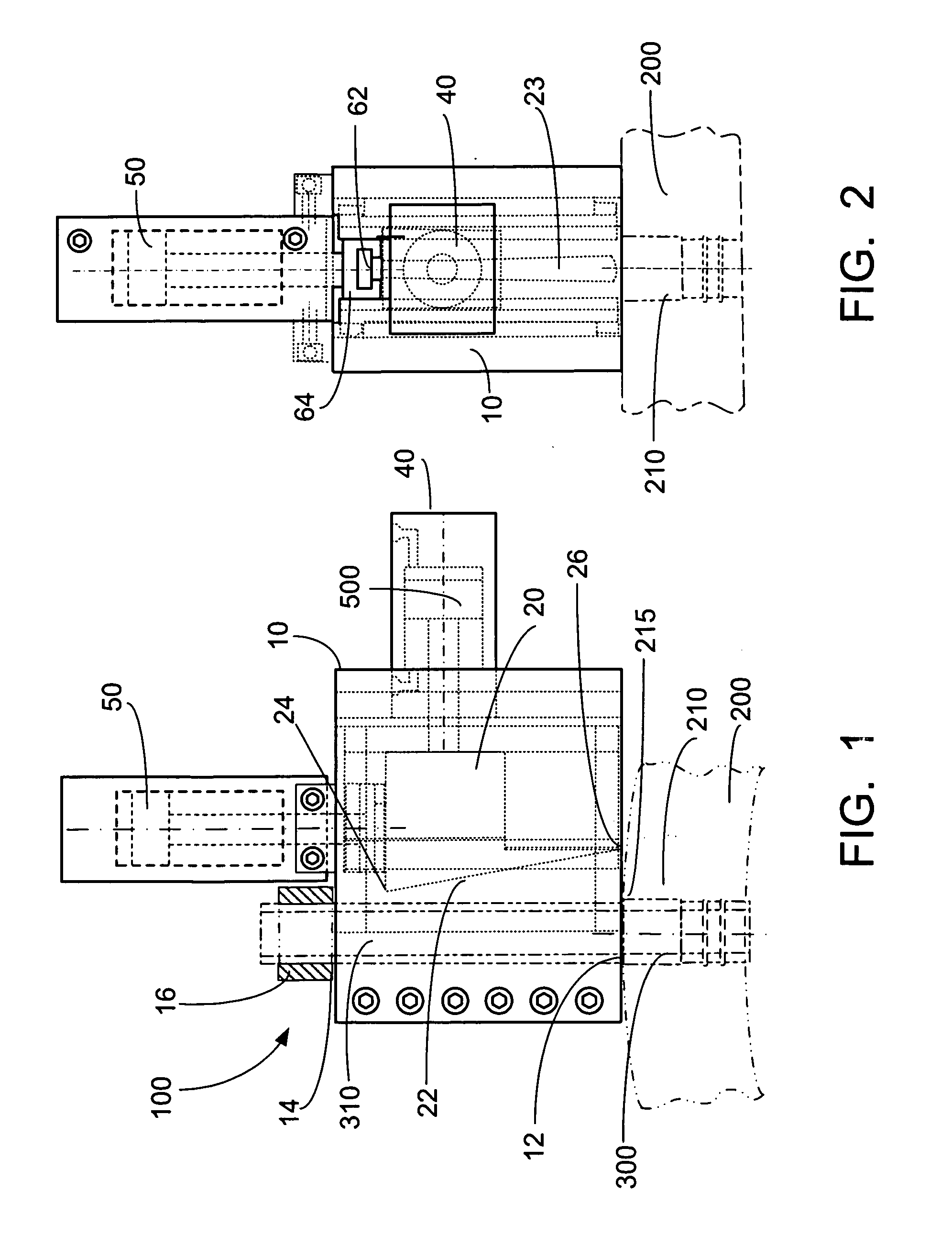
[0024]Referring now to the drawings, in which like reference numerals are used to refer to the same or similar elements, FIG. 1 shows a side view of the tube extracting device 100. The device has a housing 10 preferably comprised of two parts connected by typical fasteners, such as bolts 11. The housing 10 is supported on an external surface of a drum 200 of a typical boiler, heat exchanger or the like. The drum 200 houses conventional tube(s) 300 in tube holes 210. The tubes 300 are typically expanded into the tube holes 210 thereby forming a joint 215 between the tube 300 and the tube hole 210.

[0025]A tube stub 310 extends out of the tube hole 210. The housing 10 has a bottom opening 12 and a top opening 14 which receive the tube stub 310. The tube stub 310 exits the housing 10 from the top opening 14.

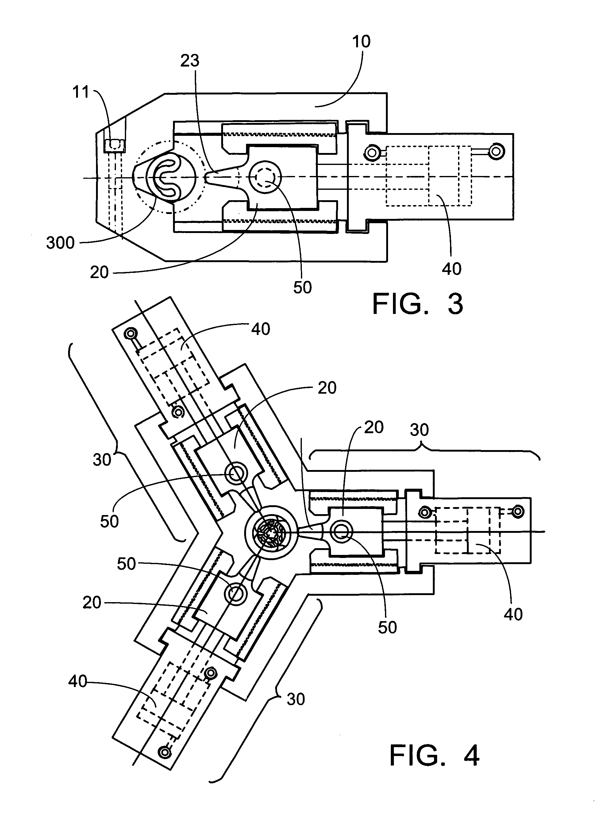
[0026]A wedge 20 is slidably mounted in the housing 10. The wedge 20 has a face 22 adjacent the portion of the tube stub 310. The face 22 of the wedge 20 preferably has a curved cont...


PUM

PropertyMeasurementUnit
diameteraaaaaaaaaa
areasaaaaaaaaaa
pressure forcesaaaaaaaaaa

Abstract

A tube extraction device which facilitates the removal of a tube from a tube hole in a drum. The tube extraction device comprises a housing which is mounted over an exterior surface of the drum. The housing has an opening which receives a removed part of the tube. A wedge having a slanted face and a bottom edge is slidably mounted in the housing. At least one side thrusting ram and at least one drive down ram are slidably mounted in the housing. The side thrusting ram laterally moves the wedge so that the slanted face indents the tube inwardly, while the drive down ram drives the wedge down into the tube so that the tube collapses in the tube hole.

Description

FIELD AND BACKGROUND OF INVENTION[0001]The present invention relates generally to the field of tube extracting devices, and more particularly to an improved tube extracting device for facilitating the removal of tubes from different types of structures, such as boilers, condensers, evaporators, and the like.[0002]A typical condenser comprises a pair of parallel tube sheets, a plurality of baffle plates, and a plurality of heat exchanger tubes. The tube sheets are located at the ends of the condenser. The baffle plates are positioned between the tube sheets and generally parallel thereto. The heat exchanger tubes extend between the tube sheets and through the baffle plates and are supported by the tube sheets. The tube sheets and baffle plates have a series of aligned holes formed therein, and the heat exchanger tubes are inserted through these holes and then expanded in the areas of the tube sheets into fluid-tight pressure contact therewith.[0003]Because of malfunctions or normal p...

Claims


Application Information

Patent Timeline
Patent Type & Authority Patents(United States)
IPC IPC(8): B23P19/04
CPCB21D41/04B23P19/025Y10T29/53961Y10T29/5383
Inventor GRAY, LUKE G. M.
Owner BABCOCK & WILCOX CANADA LIMITED
Why Eureka
Try Eureka