Internal combustion engine traction drive with electric cutting unit drive for walking greens mower

a technology of electric cutting unit and combustion engine, which is applied in the field of green mowers, can solve the problems of preventing quick and convenient variation of clip rate, affecting the efficiency of greens mowers, etc., and achieving the effect of facilitating quick and convenient modification of clip rate and clip rate of particular greens mowers, and reducing the cost of maintenance and repair

Active Publication Date: 2007-01-30
ELECTRONICS & TELECOMM RES INST +1
View PDF144 Cites 28 Cited by
  • Summary
  • Abstract
  • Description
  • Claims
  • Application Information

AI Technical Summary

Problems solved by technology

However, there are a number of disadvantages associated with the use of a greens mower employing an internal combustion engine to power both the drive mechanism and the mowing unit.
As will be appreciated by one skilled in the art, traditionally internal combustion powered greens mowers have a first disadvantage of preventing quick and convenient variation of the clip rate, because of the fixed mechanical relationship between the drive mechanism and the mowing unit.
In other words, the fixed gear ratio defined by the drive belts, gears, and / or chains does not facilitate quick and convenient modifying of the clip rate without the changing of gear members or the use of variable transmissions.
Consequently, the clip rate of a particular greens mower is often unchangeable without considerable time and effort.
However, it should be appreciated that the mechanical drive unit extending between the internal combustion engine and the articulating mowing unit is often complex and cumbersome due to the inherent need to continually provide drive power as the mowing unit articulates relative to the engine.
Still further, such conventional greens mowers often employ complex disengagement systems that the operator is required to actuate in order to engage and disengage the mowing unit.
These systems often require the operator to actuate a lever separate from the handle, which may lead to undesirable cutting performance as the mowing unit is being disengaged.

Method used


Image

  • Internal combustion engine traction drive with electric cutting unit drive for walking greens mower
  • Internal combustion engine traction drive with electric cutting unit drive for walking greens mower

Examples


Embodiment Construction

[0014]The following description of an example embodiment is merely exemplary in nature and is in no way intended to limit the invention, its application, or uses.

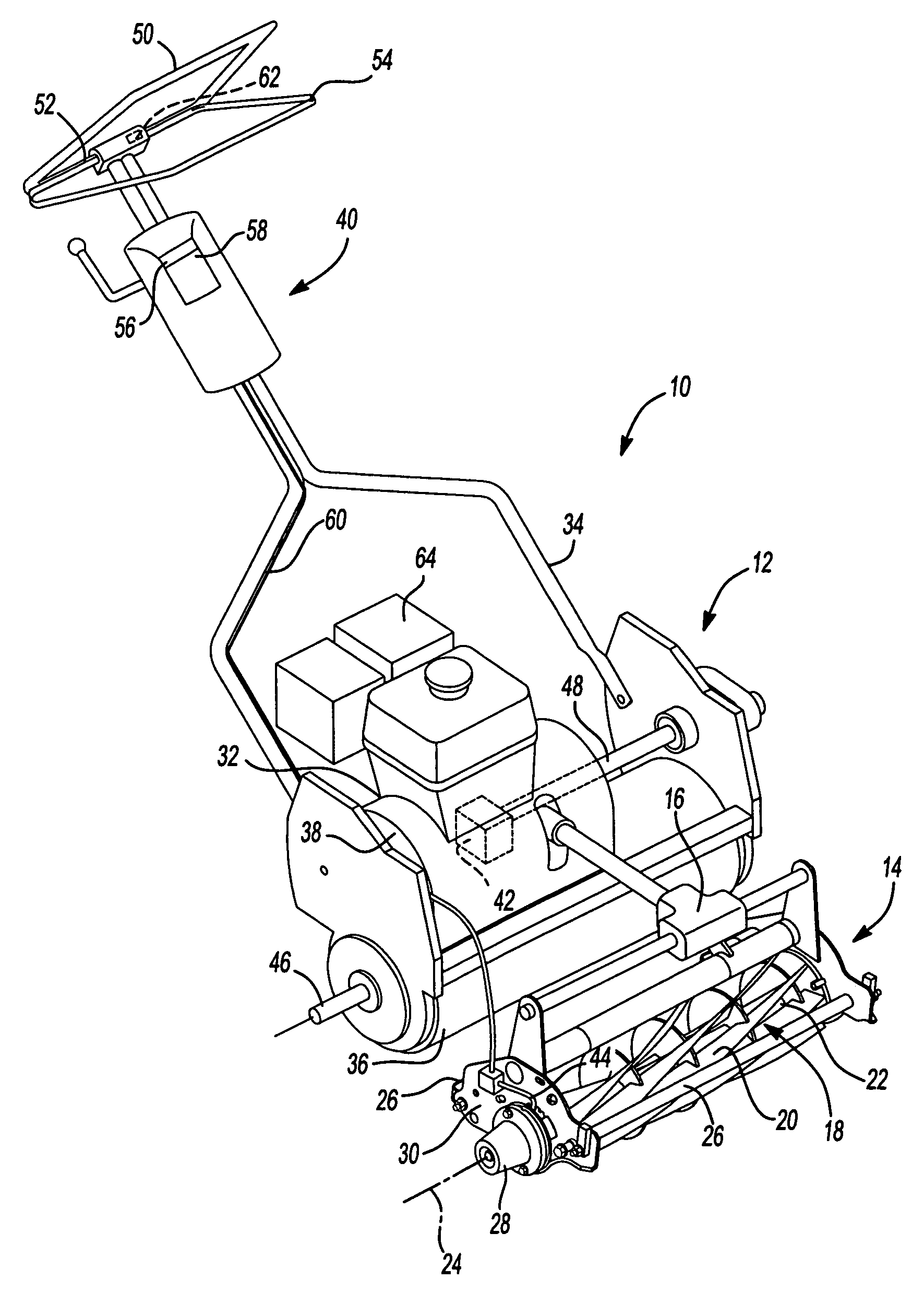
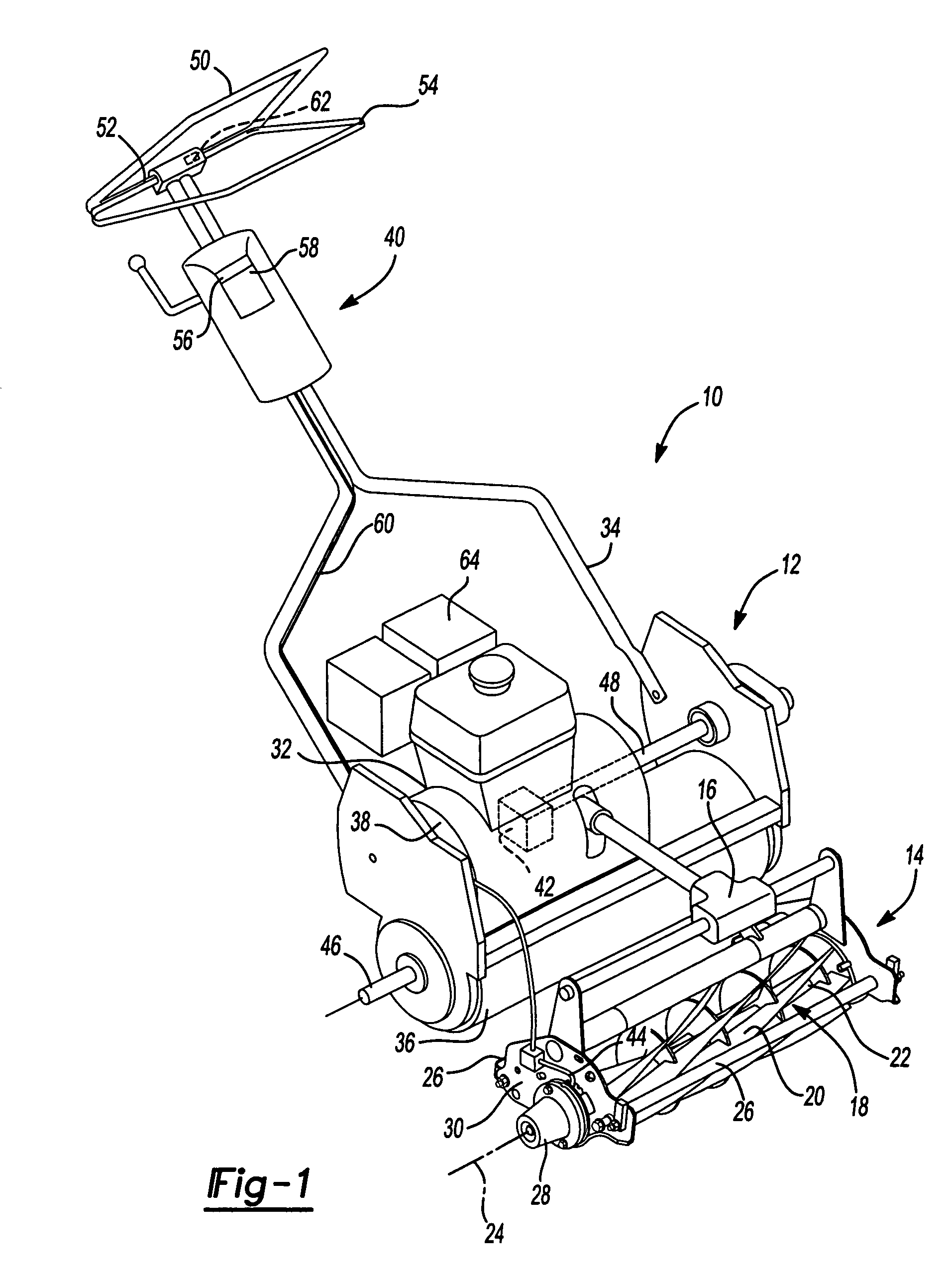
[0015]With reference to the figure, FIG. 1 illustrates a greens mower 10 incorporating the principles of the present invention. Greens mower 10 is a reel-type mower having a base portion 12 and a floating or articulating mowing unit 14. Mowing unit 14 is articulately coupled to base portion 12 through a pivoting mechanism 16.

[0016]Mowing unit 14 includes a rotatable greens mower reel 18 having spiraled blades 20 equally spaced around a reel shaft 22. Reel shaft 22 is generally elongated and defines a rotation axis 24 extending along the length of reel shaft 22. A conventional fixed bed knife (not shown) is operably mounted to mowing unit 14. Blades 20 orbit relative to shaft 22 and move past the fixed bed knife for the usual and well-known function of cutting the grass. Mowing unit 14 further includes a pair of ground engag...


PUM


Abstract

A walk-behind greens mower having a mobile structure and a ground engaging traction member rotatably coupled to the mobile structure. The ground engaging traction member imparts traction movement to the mobile structure for movement on the ground at a ground speed. An internal combustion engine is supported on the mobile structure and outputs a driving force to the ground engaging traction member. A bed knife is supported by the mobile structure having a cutting edge that cooperates with a grass cutting reel rotatably supported on the mobile structure. An electric motor supported on the mobile structure rotatably driving the grass cutting reel at a rotational speed that can vary depending upon the detected ground speed.

Description

FIELD OF THE INVENTION[0001]An example embodiment of the present invention in general relates to a greens mower having an internal combustion engine traction drive and an electric cutting unit drive.BACKGROUND OF THE INVENTION[0002]As is known in the prior art, greens mowers are particularly useful in mowing golf course greens, which are known to require exacting mowing results to assure that the grass is cut consistently throughout the green. Traditionally, these greens mowers are either walk-behind type mowers or riding mowers.[0003]Greens mowers generally employ a reel type mowing unit as opposed to a rotary type mowing unit. The clip rate of these reel type mowing units are of utmost concern due to the fact that the clip rate often determines the consistency and quality of the cut, which leads to improved turf health. Because of the time required to grow a mature green and the cost associated with therewith, it is extremely important that greens mowers operate properly and not d...

Claims


Application Information

Patent Timeline
Patent Type & Authority Patents(United States)
IPC IPC(8): A01D34/53A01D34/47A01D34/58A01D34/78
CPCA01D34/47A01D34/78A01D34/58A01D34/77
Inventor DERBY, V, HARRY L.HOLBY, BRYAN E.
Owner ELECTRONICS & TELECOMM RES INST
Why Eureka
Try Eureka