Airbag apparatus

a technology of airbags and airbags, which is applied in the direction of vehicular safety arrangements, pedestrian/occupant safety arrangements, vehicle components, etc., can solve the problems of maintaining the pressure in the lower chamber at a high level for a long time, and achieve the effect of reducing the number of holes

Active Publication Date: 2007-01-30
JOYSON SAFETY SYST JAPAN GK
View PDF37 Cites 67 Cited by
  • Summary
  • Abstract
  • Description
  • Claims
  • Application Information

AI Technical Summary

Benefits of technology

[0010]According to the first aspect of the present invention, an airbag apparatus includes an airbag including an occupant-side surface facing an occupant when deployed, and a vehicle-body-side surface opposite to the occupant-side surface, and having an interior divided into a plurality of chambers including at least two chambers, i.e. an upper chamber and a lower chamber; a gas generator for deploying the airbag; and a gas distributor enclosing the gas generator and including outlet ports for allowing gas from the gas generator to flow into at least the upper chamber and the lower chamber. The outlet port of the gas distributor for the lower chamber has an opening larger than that of the outlet port thereof for the upper chamber, and a check valve is provided for preventing the gas from flowing from the lower chamber to the upper chamber.
[0011]In the first aspect of the present invention, the airbag apparatus has the outlet port for the lower chamber having an opening larger than that of the outlet port for the upper chamber. Therefore, the lower chamber is deployed earlier than the upper chamber, and an internal pressure of the lower chamber is higher than that of the upper chamber. In addition, the gas is prevented from flowing from the lower chamber to the upper chamber by the check valve. Therefore, the pressure in the lower chamber is maintained at a high level for a long time. The airbag apparatus can protect the occupant in the case of not only a side collision, but also an overturn.
[0012]According to the first aspect of the present invention, the gas distributor is formed of a sheet wrapping the gas generator. The outlet port of the gas distributor for the lower chamber extends toward the lower chamber more than the gas generator, so that the extended portion constitutes the check valve. With this construction, the gas distributor includes the check valve, thereby making the configuration simple and reducing a manufacturing cost.

Problems solved by technology

Therefore, the pressure in the lower chamber is maintained at a high level for a long time.

Method used


Image

  • Airbag apparatus
  • Airbag apparatus
  • Airbag apparatus

Examples


Embodiment Construction

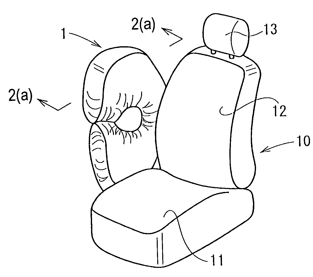
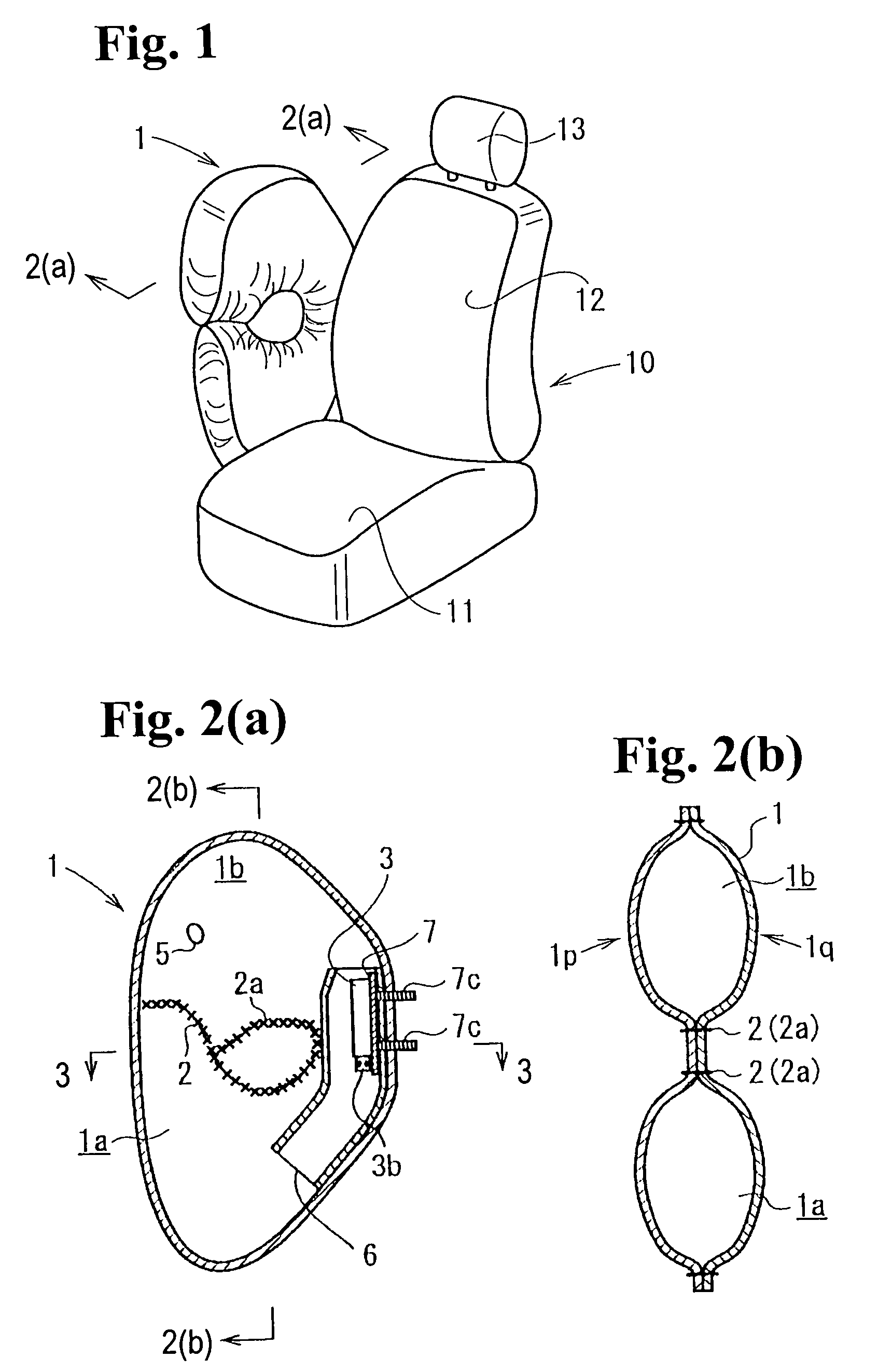
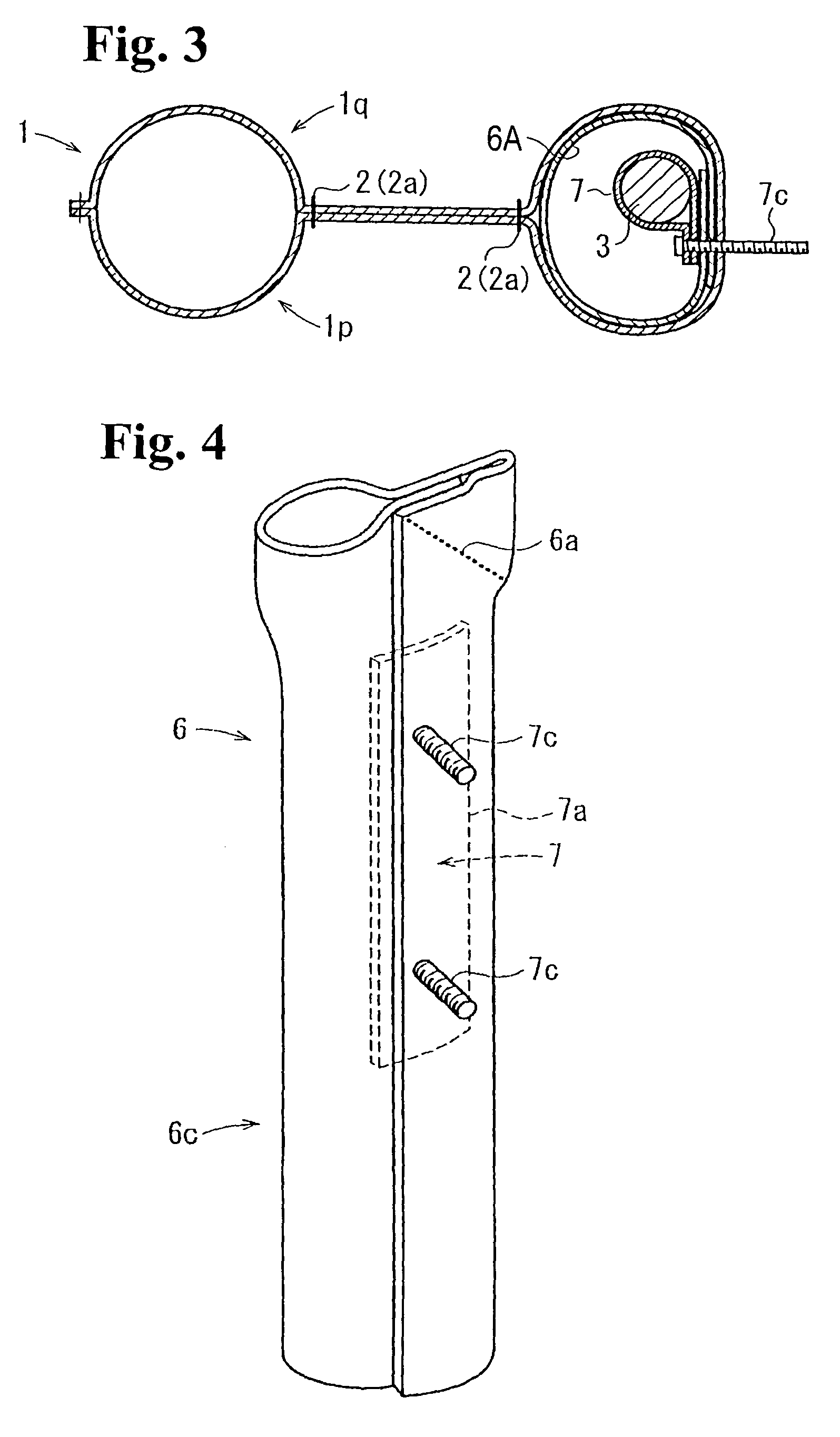
[0041]Hereunder, embodiments of the first aspect of the present invention will be explained with reference to the accompanying drawings. FIG. 1 is a perspective view of a seat of a vehicle provided with an airbag apparatus for a side collision according to the present invention. FIG. 2(a) is a cross sectional view taken along line 2(a)—2(a) in FIG. 1, and FIG. 2(b) is a cross-sectional view taken along line 2(b)—2(b) in FIG. 2(a). FIG. 3 is a cross sectional view taken along line 3—3 in FIG. 2(a). FIG. 4 is a perspective view of a gas distributor used for the airbag apparatus. FIG. 5 is a perspective view of a gas generator and a holder of the airbag apparatus. FIG. 6 is a cross sectional view taken along line 6—6 in FIG. 5.

[0042]As shown in FIG. 1, an airbag 1 is constructed to be deployed along a window side of a seat 10. The seat 10 is provided with a seat cushion 11, a seat back 12, and a headrest 13. A case (not shown) of an airbag apparatus is mounted to a side of the seatback...


PUM


Abstract

An airbag apparatus includes an airbag having an occupant-side surface and a vehicle-body-side surface opposite to the occupant-side surface when the airbag is inflated, and at least an upper chamber and a lower chamber separated from each other; a gas generator for deploying the airbag; and a gas distributor enclosing the gas generator and having outlet ports for allowing gas from the gas generator to flow into the upper chamber and the lower chamber. A check valve is provided for preventing the gas from flowing from the lower chamber to the upper chamber.

Description

BACKGROUND OF THE INVENTION AND RELATED ART STATEMENT[0001]The present invention relates to an airbag apparatus for protecting an occupant in a vehicle in case of a side collision, a roll over, and the like. More specifically, the present invention relates to an airbag apparatus having an airbag with an interior divided into a plurality of chambers.[0002]An airbag apparatus for a side collision is known in which an airbag is deployed at a side of an occupant by a gas inflator, so that the deployed airbag receives the occupant.[0003]Japanese Patent Publication (Kokai) No. 2000-177527 has disclosed a configuration in which a lower portion of an airbag is deployed with an internal pressure higher than that of an upper portion for receiving a lumbar region, or a middle part, of the occupant.[0004]FIG. 15 is a side view of a seat having the airbag apparatus for a side collision disclosed in Japanese Patent Publication (Kokai) No. 2000-177527, and FIG. 16 is an enlarged cross sectional vi...

Claims


Application Information

Patent Timeline
Patent Type & Authority Patents(United States)
IPC IPC(8): B60R21/16B60R21/207B60R21/231B60R21/233B60R21/2338B60R21/26B60R21/261
CPCB60R21/207B60R21/23138B60R21/233B60R21/261B60R21/2338B60R2021/23382B60R2021/23316B60R2021/23324
Inventor KUMAGAI, MASAYOSHIJOUJIMA, KAZUHIKOTSUJIMOTO, KEI
Owner JOYSON SAFETY SYST JAPAN GK
Why Eureka
Try Eureka