Air driven hydraulic pump

Active Publication Date: 2007-01-30
PSG CALIFORNIA LLC
View PDF15 Cites 55 Cited by
  • Summary
  • Abstract
  • Description
  • Claims
  • Application Information

AI Technical Summary

Benefits of technology

[0012]Accordingly, it is an object of the present invention to provide an improved air

Problems solved by technology

However, air driven hydraulic pumps are ancillary systems to hydraulic

Method used


Image

  • Air driven hydraulic pump
  • Air driven hydraulic pump
  • Air driven hydraulic pump

Examples


Embodiment Construction

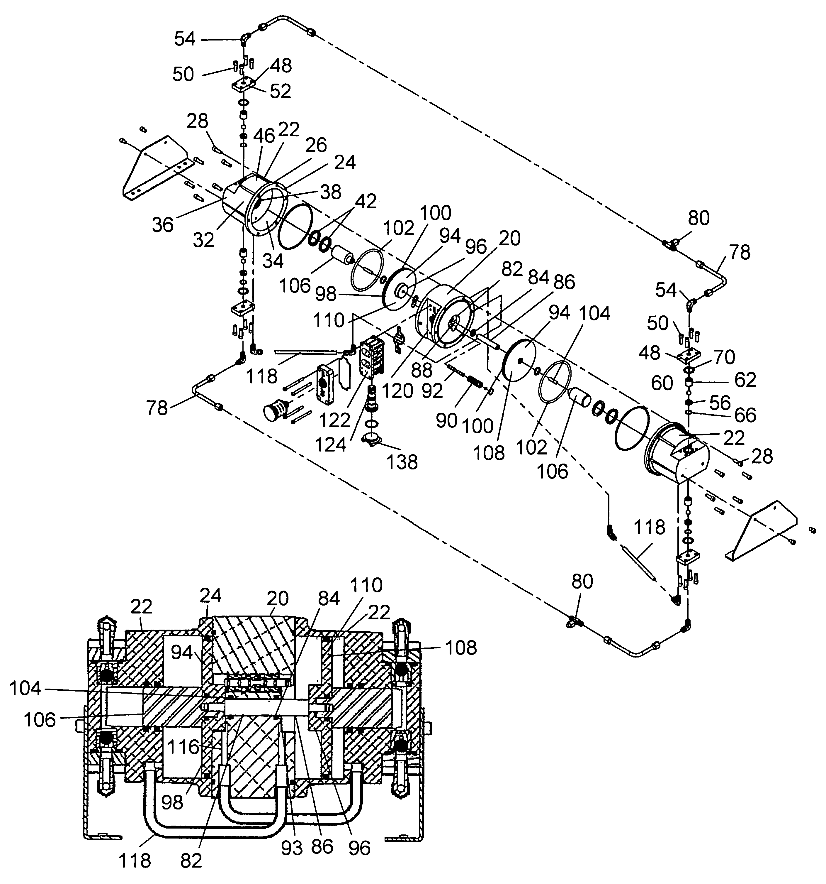
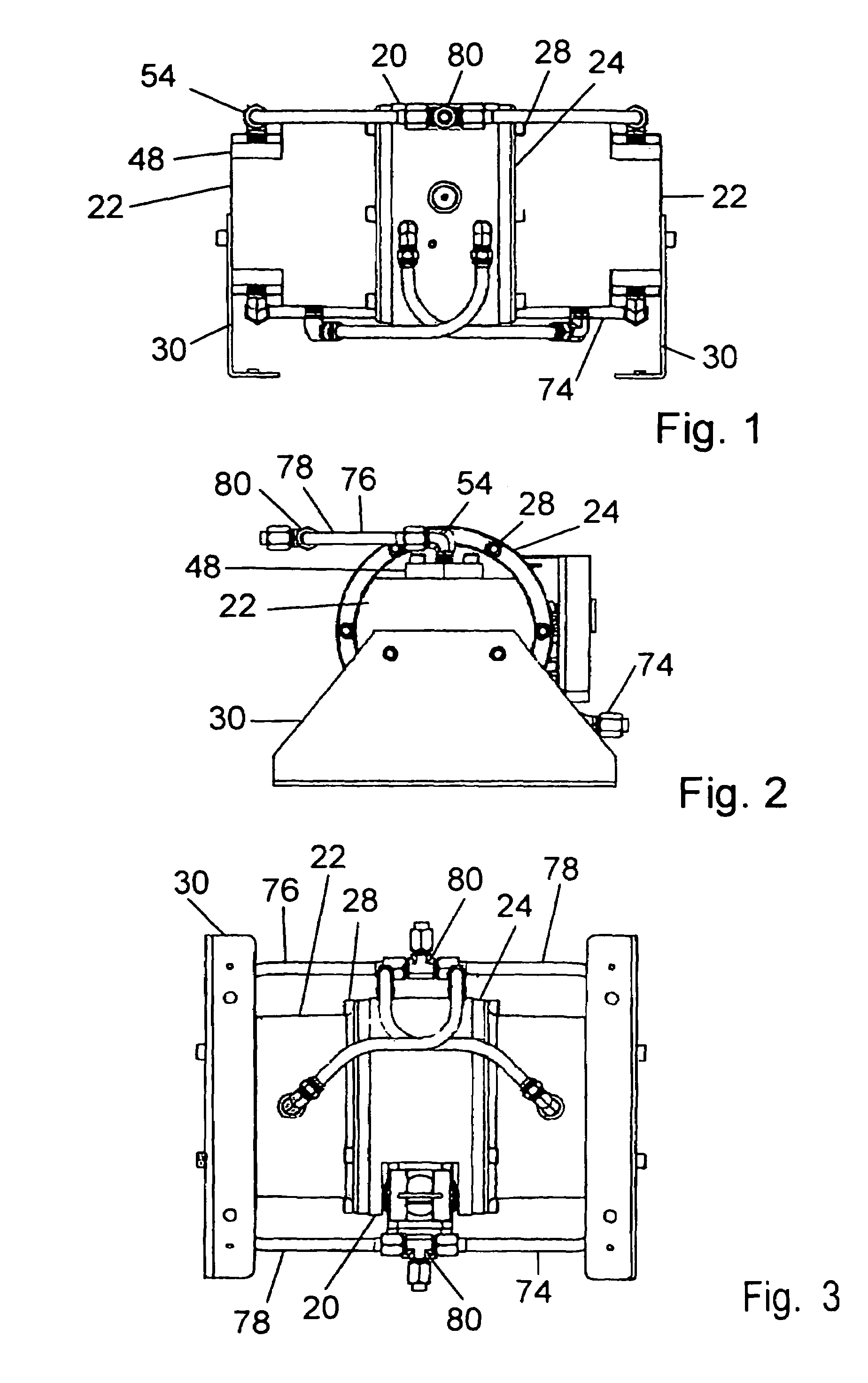
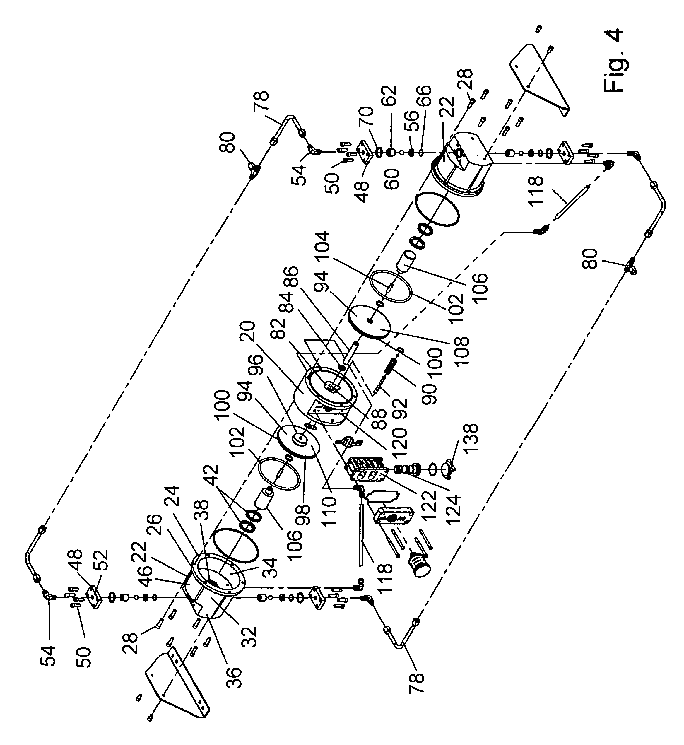
[0027]Turning in detail to the figures, an air driven hydraulic pump is illustrated. The pump structure includes a structural center section 20 with opposed integral cylinder / cylinder head units 22. Each cylinder / cylinder head unit 22 includes a circular mounting flange 24 with mounting holes 26 extending through the flange 24. The center section 20 includes tapped holes for receipt of bolts 28 positioned in the mounting holes 26 to securely affix the units 22 to the center section 20. Sheet metal feet 30 fastened to the ends of the units 22 extend at either end of the pump to define a mounting plane.

[0028]The cylinder / cylinder head units 22 are conveniently identical. Each unit 22 includes a cylinder 32 having a bore 34 concentrically therethrough to provide a pneumatic cylinder. The mounting flange 24 is at one end of the cylinder 32. At the other end, a cylinder head 36 closes the cylinder 32. The head 36 is integrally formed with the cylinder 32 and includes a concentric bore 38...


PUM


Abstract

An air driven hydraulic pump includes two opposed cylinders to either side of a center section. Two pneumatic pistons are slidable in the opposed cylinders and are coupled with one another by a common shaft extending through the center section. The pneumatic pistons ride in the opposed pneumatic cylinders and include hydraulic plungers extending therefrom. Cylinder heads integral with the cylinders provide hydraulic cylinders aligned with the hydraulic plungers. An air valve delivers pneumatic pressure to alternate sides of both pneumatic pistons such that the forces on the pistons are additive alternately in each direction.

Description

BACKGROUND OF THE INVENTION[0001]The field of the present invention is hydraulic pumps which are air driven.[0002]Reciprocating air driven pumps are well known. Reference is made to U.S. Pat. Nos. 5,213,485; 5,169,296; and 4,247,264. Actuator valves using feed-back control systems are disclosed in U.S. Pat. Nos. 4,549,467 and 5,957,670. Another mechanism to drive an actuator valve is by solenoid such as disclosed in U.S. Pat. No. RE 38,239[0003]Pumps using the above technology have been devised to increase pumping pressure. Reference is made to U.S. Pat. No. 5,927,954 which includes a power amplifier piston centered between two diaphragms.[0004]The foregoing patents are double diaphragm pumps. Opposed piston pumps driven by an air cylinder are also known. Reference is made to U.S. Pat. No. 5,415,531. In addition to the reciprocating air cylinder driving opposed pistons, the pumping cylinders are shown to be smaller in diameter than the air cylinder in this patent. Consequently, the ...

Claims


Application Information

Patent Timeline
IPC IPC(8): F04B43/06F04B45/00
CPCF04B9/135F04B9/133
Inventor WEST, TODD M.KENNEDY, DENNIS E.
Owner PSG CALIFORNIA LLC
Why Eureka
Try Eureka