Apparatus and method for placing spacers in an emissive display

a technology of emissive display and spacer, which is applied in the manufacture of photo-emissive cathodes, non-emitting electrodes, electrode systems, etc., can solve the problems of shortening the conductor of the column or row, destroying the emitter, and insufficient structural strength of the thin plate to preven

Inactive Publication Date: 2007-01-30
MOTOROLA INC
View PDF2 Cites 1 Cited by
  • Summary
  • Abstract
  • Description
  • Claims
  • Application Information

AI Technical Summary

Problems solved by technology

These thin plates are not structurally sufficient to prevent collapse or bowing upon evacuation of the interspace region.
This method has the disadvantage of spacer misalignment when contacting the cathode resulting in destruction of emitters and shorted column or row conductors.
Other disadvantages of prior art schemes include large processing times required to heat display plate and spacers, oxidation of cathode bonding metals associated with high temperatures and glues thereby impacting the quality of the vacuum, and contamination caused by elaborate pick and place equipment required for spacer placement.
Furthermore, the spacers may be troublesome to keep in an upright position while installing the second plate, and the pick and place method consumes valuable time, perhaps as much as 30 minutes for a large array.

Method used


Image

  • Apparatus and method for placing spacers in an emissive display
  • Apparatus and method for placing spacers in an emissive display
  • Apparatus and method for placing spacers in an emissive display

Examples


Embodiment Construction

[0015]The following detailed description of the invention is merely exemplary in nature and is not intended to limit the invention or the application and uses of the invention. Furthermore, there is no intention to be bound by any theory presented in the preceding background of the invention or the following detailed description of the invention.

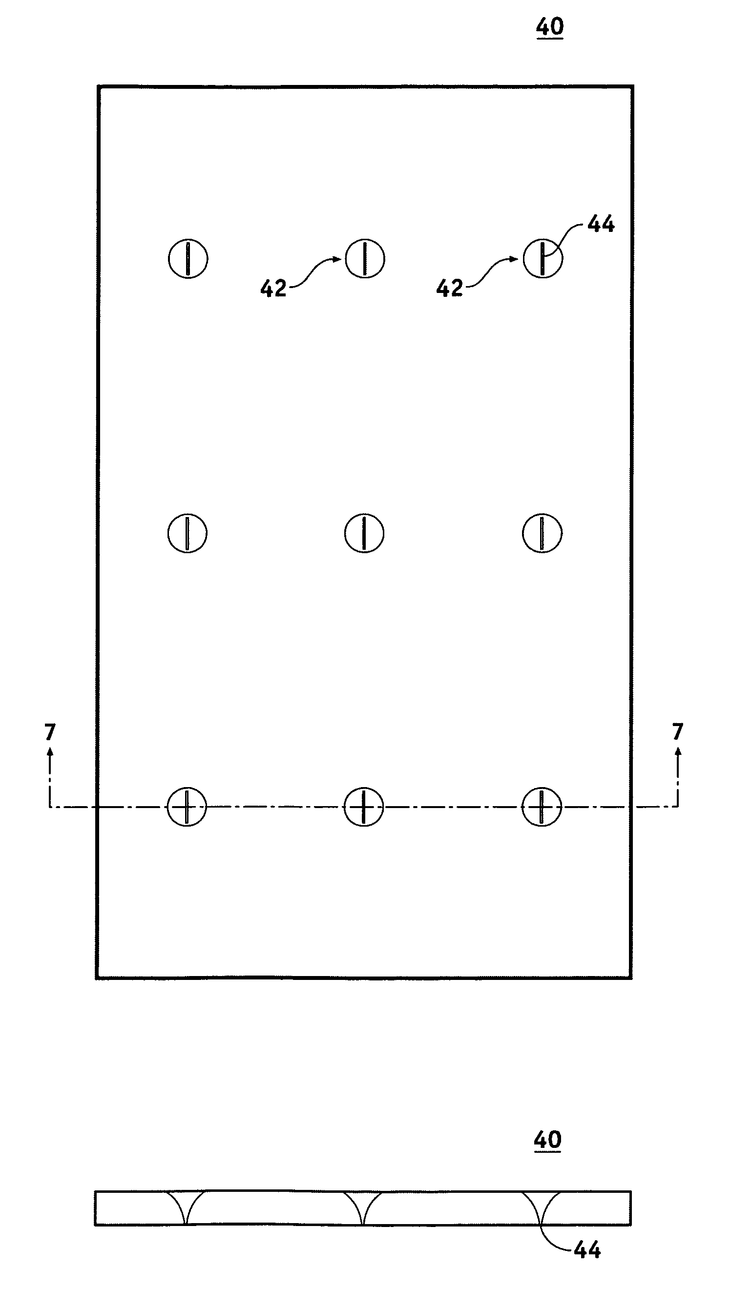
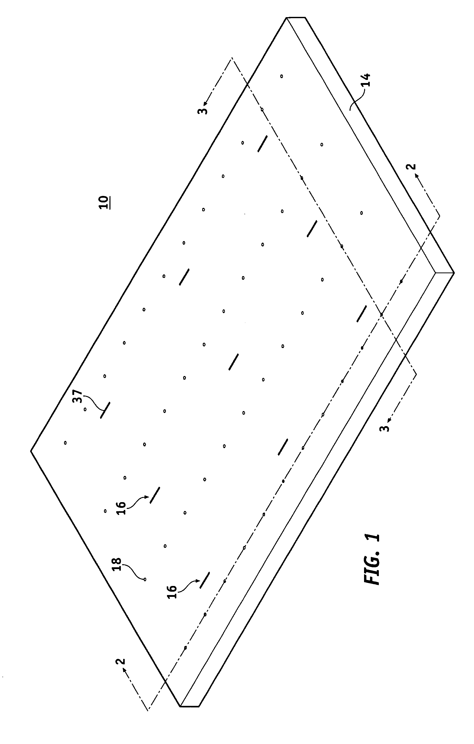
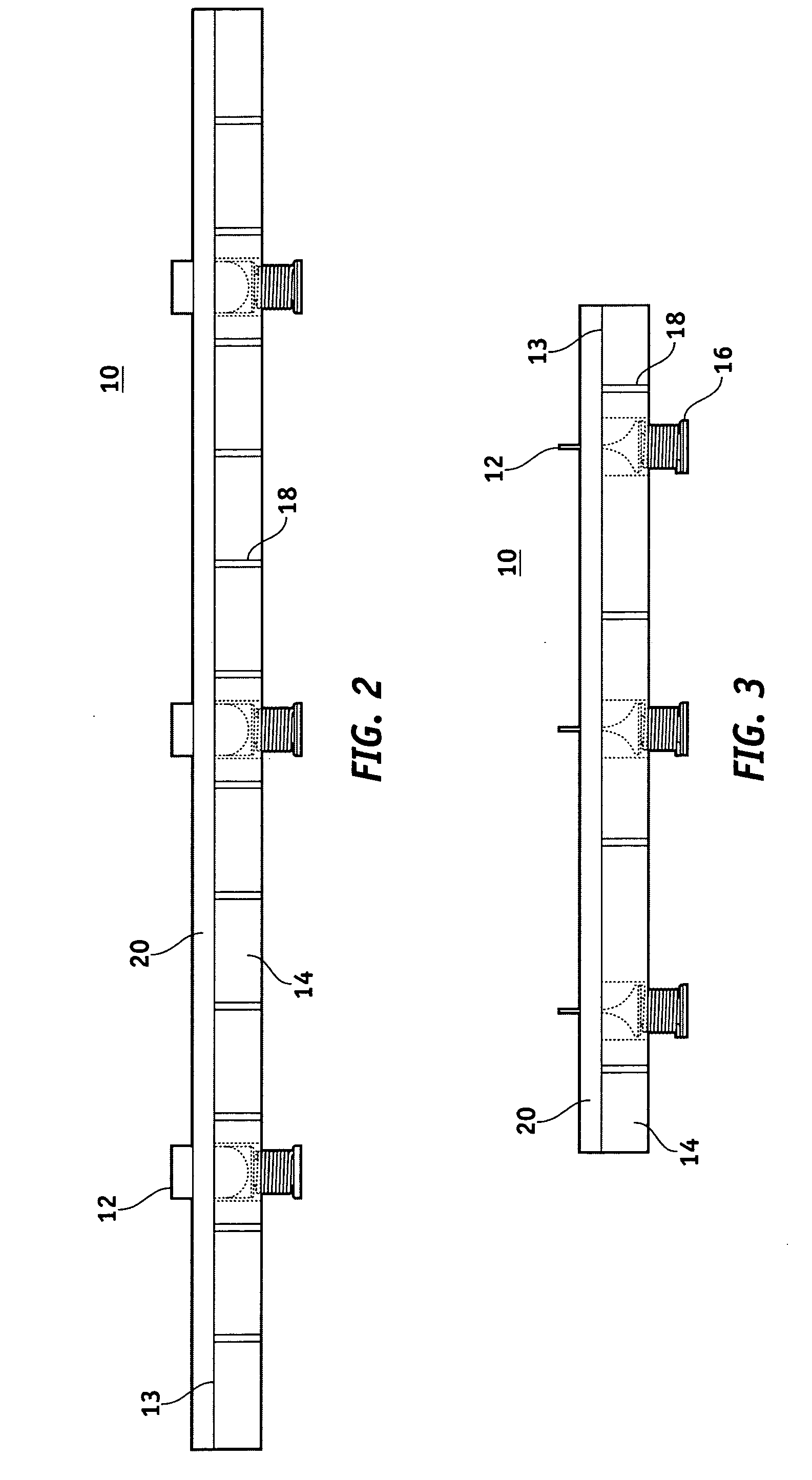
[0016]Referring to FIGS. 1–3, the apparatus 10 in accordance with a preferred embodiment of the invention provides a method for providing separation between a cathode and anode of an emission display by placing spacers 12 in the evacuated interspace region between the anode and cathode. A base 14 is configured for securing a plurality of electromagnets 16. The base 14 may comprise any type of material such as plastic or ceramic, but preferably would comprise a thermoset plastic in order to ensure dimensional stability. While a three by three array of electromagnets 16 is shown for simplicity of description, the number of electromagnets 16 wo...


PUM


Abstract

An apparatus (10) for, and method of, placing a plurality of spacers (12) between a parallel opposed anode and cathode (20) of an emissive display includes temporarily securing, by applying a vacuum for example, a first side of one of the anode or cathode to a base (14) having a plurality of electromagnets (16) positioned therein. The electromagnets (16) attract a first side of each of the plurality of spacers (12), thereby positioning each of the spacers (12) in a desired location on a second side of the one of the anode or cathode (20). The spacers (12) may be provided from a shuffling tray (40) having a plurality of openings (42), each opening (42) approximately aligned with one of the electromagnets (16) and shaped so as to present the first side to the electromagnet (16) to the one of the anode or cathode (20).

Description

FIELD OF THE INVENTION[0001]The present invention generally relates to emission displays, and more particularly to a structure for, and method of, affixing spacers in field emission displays.BACKGROUND OF THE INVENTION[0002]Spacers for field emission displays are known in the art. A field emission display includes an envelope structure having an evacuated interspace region between two display plates. Electrons travel across the interspace region from a cathode plate, upon which electron emitter structures, such as Spindt or carbon nanotubes, are fabricated, to an anode plate which includes deposits of light-emitting materials, or phosphors. Typically the pressure within the interspace region is less than or equal to 10−6 Torr.[0003]The cathode plate and anode plate are thin in order to provide low display weight. These thin plates are not structurally sufficient to prevent collapse or bowing upon evacuation of the interspace region. Spacers are structures positioned between the anod...

Claims


Application Information

Patent Timeline
Patent Type & Authority Patents(United States)
IPC IPC(8): H01J9/00
CPCH01J9/185
Inventor JOHNSON, SCOTT V.HAGEN, CARL R.
Owner MOTOROLA INC
Why Eureka
Try Eureka