Trocar and trocar system

a trocar and trocar technology, applied in trocars, medical science, surgery, etc., can solve the problems of time-consuming, difficult and time-consuming work, and unstable operation of trocar apparatus, and achieve the effect of convenient and quick insertion, easy and stable operation

Inactive Publication Date: 2007-02-06
OLYMPUS CORP
View PDF8 Cites 70 Cited by
  • Summary
  • Abstract
  • Description
  • Claims
  • Application Information

AI Technical Summary

Benefits of technology

[0016]Another object of the invention is to provide a trocar system wherein when a small-diameter pierce hole made by a trocar needle is increased up to an outside diameter of a tube, an organ in the abdominal cavity, for instance, is not pressed and the tube can easily and quickly be inserted and stayed in the body wall, and also the work for inserting a distal end portion of the trocar needle can be easily and stably performed.

Problems solved by technology

In such a case, a time-consuming work is required.
Consequently, when the trocar needle is made to piece the patient's body wall, the engagement between the proximal end portion of the tube and the proximal end portion of the trocar needle may be released if the user holds the trocar apparatus at an undesirable position.
As a result, the operation of the trocar apparatus becomes unstable.
This work is difficult and time-consuming.

Method used


Image

  • Trocar and trocar system
  • Trocar and trocar system
  • Trocar and trocar system

Examples


first embodiment

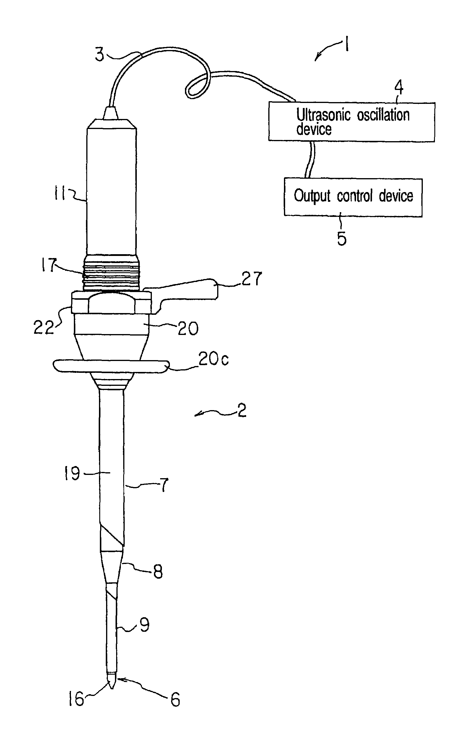
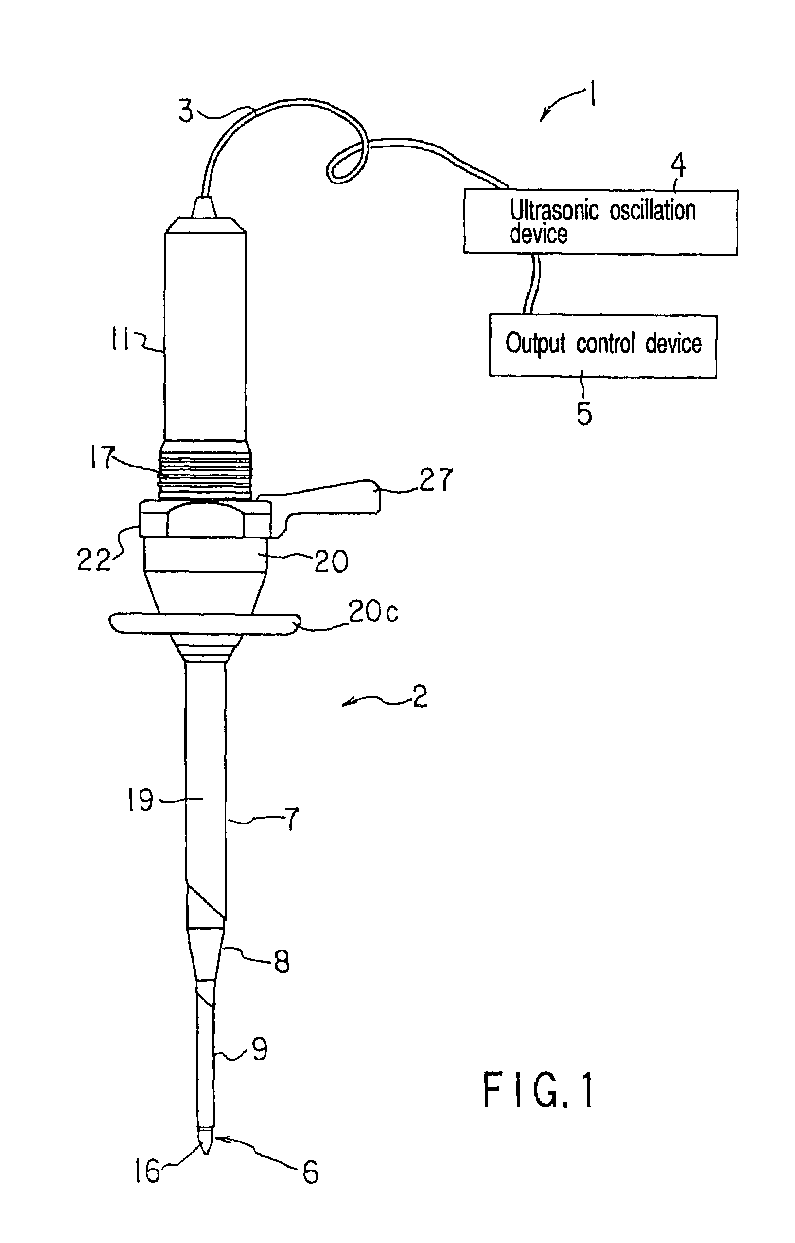
[0088]the present invention will now be described with reference to FIGS. 1 to 6B. FIG. 1 schematically shows the entire structure of a trocar system 1 according to this embodiment. This trocar system 1 is provided with a handpiece unit 2 of an ultrasonic trocar, which is held and operated by the operator. The handpiece unit 2 is connected to an ultrasonic oscillation device 4 over a connection cable 3. The ultrasonic oscillation device 4 supplies energy for ultrasonic oscillation. The ultrasonic oscillation device 4 is connected to an output control device 5, such as a foot switch or a hand switch, for controlling energy output.

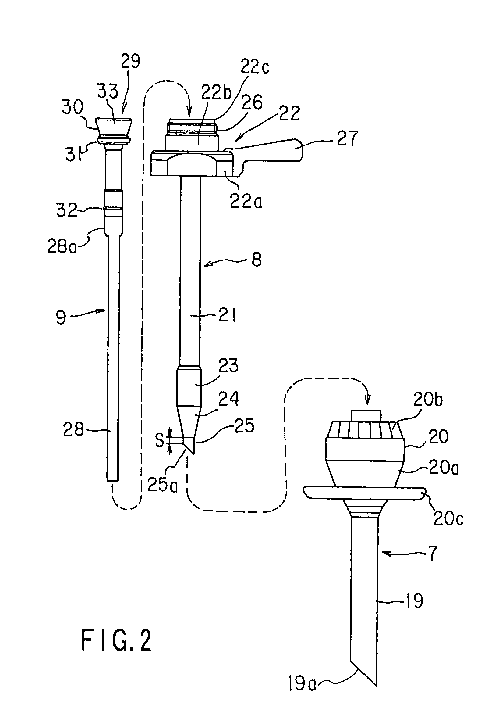
[0089]The handpiece unit 2 of the ultrasonic trocar comprises a trocar needle 6 for piercing into the body wall; a tube 7 in which the trocar needle 6 is inserted; a dilator 8 inserted between the tube 7 and trocar needle 6; and a guide member 9 formed of a soft cylindrical member and inserted in the dilator 8. The guide member 9 may be formed of a hard memb...

sixth embodiment

[0152]FIGS. 16 to 25 show the invention. FIG. 16 schematically shows the entire structure of a trocar system 201 according to this embodiment. This trocar system 201 is provided with a handpiece unit 202 of an ultrasonic trocar, which is held and operated by the operator. The handpiece unit 202 is connected to an ultrasonic oscillation device 204 over a connection cable 203. The ultrasonic oscillation device 204 supplies energy for ultrasonic oscillation. The ultrasonic oscillation device 204 is connected to an output control device 205, such as a foot switch or a hand switch, for controlling energy output.

[0153]The handpiece unit 202 of the ultrasonic trocar comprises a trocar needle 206 for piercing into the body wall; a tube 207 in which the trocar needle 206 is inserted; a dilator 208 inserted between the tube 207 and trocar needle 206; and a guide member 209 formed of a soft cylindrical member and inserted in the dilator 208. The guide member 209 may be formed of a hard member....


PUM


Abstract

A trocar has a projection portion which is a part of a tube projecting from a distal end portion of an outer tube in the state in which the tube is inserted in the outer tube, an amount of projection of the projection portion from the distal end portion of the outer tube varying in accordance with relative movement of the tube and the outer tube.

Description

CROSS-REFERENCE TO RELATED APPLICATIONS[0001]This is a Continuation Application of PCT Application No. PCT / JP01 / 10795, filed Dec. 10, 2001, which was not published under PCT Article 21 (2) in English.[0002]This application is based upon and claims the benefit of priority from the prior Japanese Patent Applications No. 2000-377866, filed Dec. 12, 2000; and No. 2001-196587, file Jun. 28, 2001, the entire contents of both of which are incorporated herein by reference.BACKGROUND OF THE INVENTION[0003]1. Field of the Invention[0004]The present invention relates to a trocar and a trocar system, wherein a trocar tube, which is to be inserted in a patient's body and used as a guide tube for an instrument inserted in the body cavity, is made to stay in a state in which the tube has pierced and penetrated the patient's skin and body wall.[0005]2. Description of the Related Art[0006]In general, in the prior art, there is used a trocar apparatus wherein a trocar tube, which is to be inserted in...

Claims


Application Information

Patent Timeline
Patent Type & Authority Patents(United States)
IPC IPC(8): A61B17/34A61B17/32
CPCA61B17/3415A61B17/3476A61B17/3417A61B17/320068A61B2017/347A61B2017/320072A61B2017/320073A61B2017/320071
Inventor ISHIKAWA, MANABU
Owner OLYMPUS CORP
Why Eureka
Try Eureka