Signal transmission cable with connector

a technology of signal transmission cable and connector, which is applied in the direction of insulated conductors, cables, coupling device connections, etc., can solve the problems of electromagnetic interference noise error, imperfect electrical connection between metal plates or between metal plates and braided shields, and achieve the effect of suppressing the current in the common mode, avoiding interference with appearance and handling, and avoiding interferen

Inactive Publication Date: 2007-02-06
FDK CORP
View PDF22 Cites 49 Cited by
  • Summary
  • Abstract
  • Description
  • Claims
  • Application Information

AI Technical Summary

Benefits of technology

[0027]It is an object of the present invention to provide a signal transmission cable with a connector, which can exert a sufficient common mode current suppression effect in a wide band without impairing appearance and handleability.

Problems solved by technology

In recent years, along with the increased processing speed in electronic equipment, errors caused by electromagnetic interference noise have become a problem.
However, when trying to reduce unnecessary electromagnetic radiation of a cable for a high-speed signal of over several hundred Mbps by use of the conventional technology as described above, the following problems were observed.
Thus, a bit error is caused by received waveform rounding in signal transmission of several hundred Mbps or more.
In actual shielded connector and shielded cable, electrical connection on a contact surface between metal plates or between a metal plate and a braided shield is not perfect.
Thus, unnecessary electromagnetic radiation is generated from the braided shield.
Consequently, a sufficient reduction effect cannot be obtained for the common mode current caused by unbalance of a differential signal.
Since a ferrite core fitted to outside of insulating coating of a cable is large and heavy, flexibility becomes poor.
Thus, not only does handling of the cable become difficult, but also the appearance thereof is impaired.
Moreover, assembly and attachment costs of the core are increased.
Furthermore, since magnetic permeability is lowered at a frequency as high as 800 MHz or more, a sufficient common mode current suppression effect cannot be obtained.
Thus, an unnecessary electromagnetic radiation reduction effect at the frequency as high as 800 MHz or more is insufficient.
However, the cable has hardly any common mode current suppression effect at a frequency of 100 MHz or less.
Thus, a reduction effect cannot be obtained for a low-frequency common mode current of a signal having a transmission rate of several hundred Mbps or more.

Method used


Image

  • Signal transmission cable with connector
  • Signal transmission cable with connector
  • Signal transmission cable with connector

Examples


Embodiment Construction

[0036]From the description in the present specification and of the accompanying drawings, at least the following will become apparent.

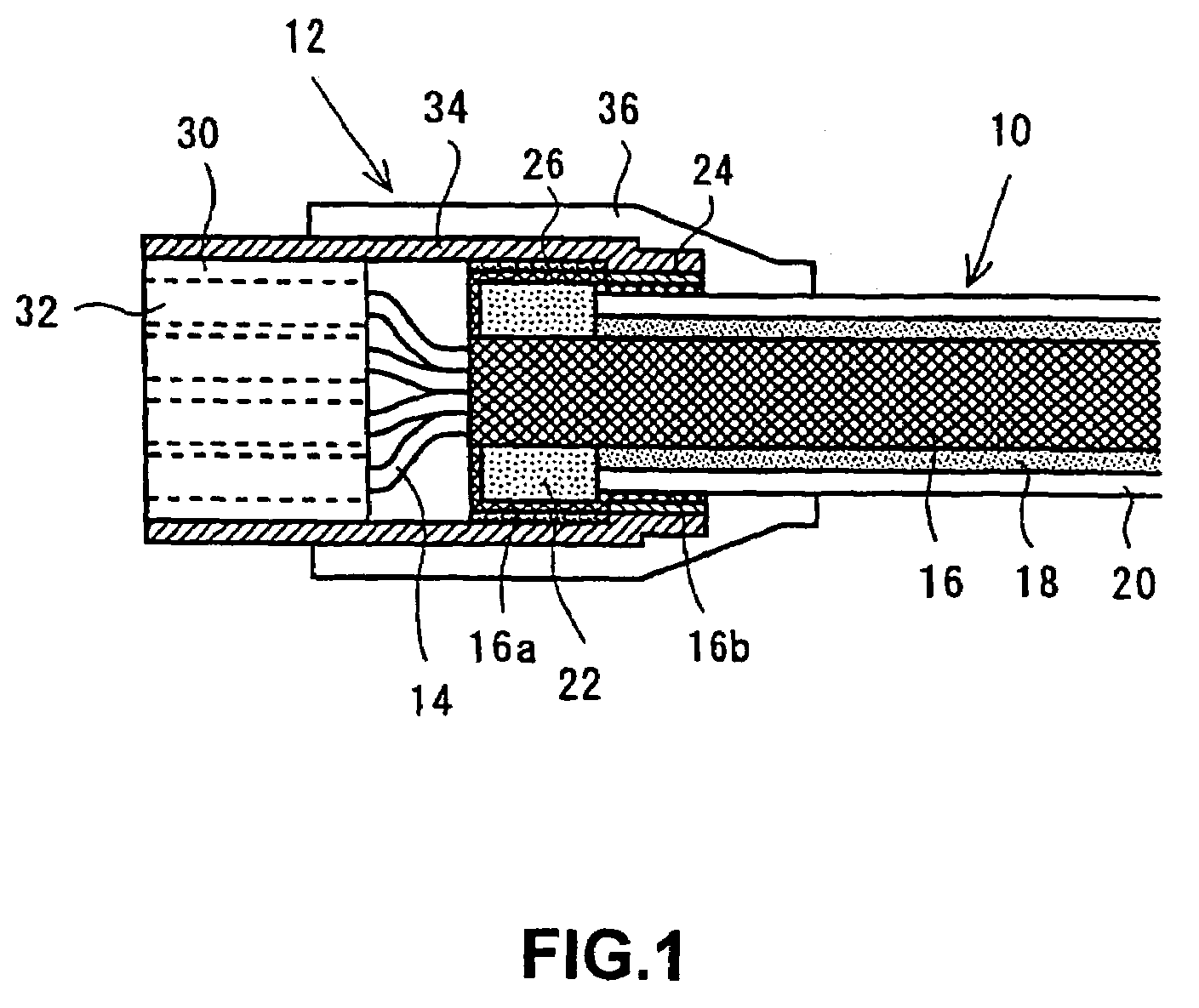
[0037]FIG. 1 is an explanatory view showing an embodiment of a signal transmission cable with a connector according to the present invention. This signal transmission cable with a connector has a configuration in which a connector 12 is electrically and mechanically connected to at least one end of a shielded cable 10.

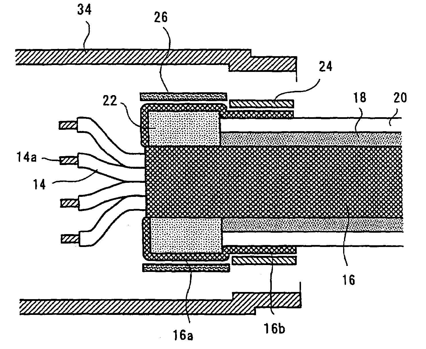
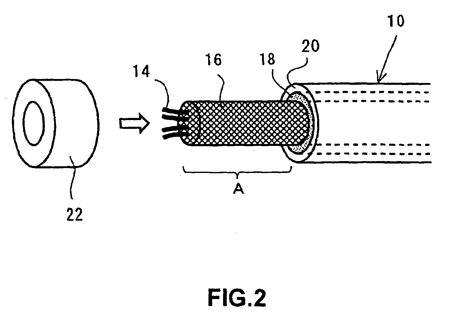
[0038]As shown in FIG. 2, the shielded cable has a structure in which a plurality of insulated wires 14 are bundled and a periphery thereof is covered with a braided shield 16 (a shielding layer formed by braiding thin copper wires into a cylinder), a ferrite compound layer 18, and an insulating coating layer 20. The ferrite compound layer 18 is a sheath obtained by mixing ferrite powder in a resin material. A ferrite toroidal core 22 (hereinafter simply referred to as a toroidal core) is fitted on a portion (indicated by reference symbo...


PUM

PropertyMeasurementUnit
frequencyaaaaaaaaaa
frequencyaaaaaaaaaa
frequencyaaaaaaaaaa

Abstract

A signal transmission cable with a connector, that includes a shielded cable having a shielding layer and an insulating coating layer, which cover a periphery of a plurality of insulated wires, and a magnetic powder compound layer interposed between the shielding layer and the insulating coating layer; a connector which is electrically and mechanically connected to at least one end of the shielded cable, and which has a shielding metal cover extending from a housing part to a cable end, the housing part holding terminals to be connected to the insulated wires; and a closed magnetic path core which is fitted on the shielding layer with the insulating coating layer partly removed at the end of the shielded cable. The shielding layer is folded back so as to cover outside of the closed magnetic path core and a tip portion of the shielding layer is connected to the shielding metal cover.

Description

CROSS-REFERENCE TO RELATED APPLICATIONS[0001]This application is a continuation of the International Application No. PCT / JP03 / 07874 filed on Jun. 20, 2003 designating the United States of America.BACKGROUND OF THE INVENTION[0002]1. Field of the Invention[0003]The present invention relates to a signal transmission cable with a connector, which requires measures against EMI (electromagnetic interference). More particularly, the present invention relates to a signal transmission cable with a connector, which can respond to noise regulations prescribed by every country without impairing appearance and handleability by combining a closed magnetic path core embedded in a folded portion of a shielding layer of a cable, and a shielded cable having a magnetic powder compound layer. This technology is useful for various signal transmission cables used in, for example, computers game machines, office equipment, portable devices, medical equipment, in-vehicle equipment, machine tools, and the l...

Claims


Application Information

Patent Timeline
Patent Type & Authority Patents(United States)
IPC IPC(8): H01B11/06H01B7/00H01R9/03H01R9/05H01R13/658H01R13/6592H01R13/719
CPCH01R9/031H01R9/032H01R13/6592H01R13/719H01R9/0524H01R13/65912
Inventor KATSUYAMA, YOSHIROKONDA, JUNJITERANISHI, MANABU
Owner FDK CORP
Why Eureka
Try Eureka