Protection device with a sandwiched cantilever breaker mechanism

a protection device and cantilever technology, applied in the direction of earth fault current operation of the protective switch, emergency protective arrangement for limiting excess voltage/current, switch details, etc., can solve the problems of low power arc between the two conductors, arc fault, ground faul

Active Publication Date: 2007-02-06
PASS SEYMOUR
View PDF36 Cites 77 Cited by
  • Summary
  • Abstract
  • Description
  • Claims
  • Application Information

AI Technical Summary

Benefits of technology

[0017]The present invention is configured to deny power to the user accessible plug receptacles when the device is tripped. Accordingly, the present invention provides a safety feature that eliminates a hazard condition that may be evident during a miswire condition of the protective device.

Problems solved by technology

An arc fault may be caused by damaged insulation on the hot line conductor or neutral line conductor, or on both the hot line conductor and the neutral line conductor.
The damaged insulation may cause a low power arc between the two conductors and a fire may result.
With regard to GFCIs, a ground fault occurs when a current carrying (hot) conductor creates an unintended current path to ground.
The unintended current path represents an electrical shock hazard.
Ground faults, as well as arc faults, may also result in fire.
First, the hot conductor may contact ground if the electrical wiring insulation within a load circuit becomes damaged.
This scenario represents a shock hazard.
For example, if a user comes into contact with a hot conductor while simultaneously contact ground, the user will experience a shock.
A ground fault may also occur when the equipment comes in contact with water.
A ground fault may also result from damaged insulation within the electrical power distribution system.
Another type of ground fault may occur when the load neutral terminal, or a conductor connected to the load neutral terminal, becomes grounded.
In other words, when the user comes into contact with a hot conductor (the first fault) at the same time as contacting a neutral conductor that has been grounded on the load side (the second fault), the user may experience serious injury or death.
However, there are drawbacks associated with hard-wiring the user accessible plug receptacles to the feed-through terminals.
However, power to the user accessible plug receptacles may not be removed if the protective device is miswired.
A miswire condition may represent a hazard to a user when a cord connected load is plugged into the user accessible receptacle included in the device.
Thus, the user is not protected if there is a fault condition in the cord-connected load.
Besides miswiring, failure of the device to interrupt a true fault condition or simulated fault condition may be due to the device having an internal fault condition, also know as an end of life condition.
Thus, if the power source of the electrical distribution system is connected to the load terminals (i.e., a line-load miswire condition), the circuit interrupting contacts will break electrical connection.
One drawback to this approach becomes evident when the protective device is not coupled to any downstream receptacles.
Accordingly, there is a need to deny power to the user accessible receptacles when the device is tripped.

Method used


Image

  • Protection device with a sandwiched cantilever breaker mechanism
  • Protection device with a sandwiched cantilever breaker mechanism
  • Protection device with a sandwiched cantilever breaker mechanism

Examples


first embodiment

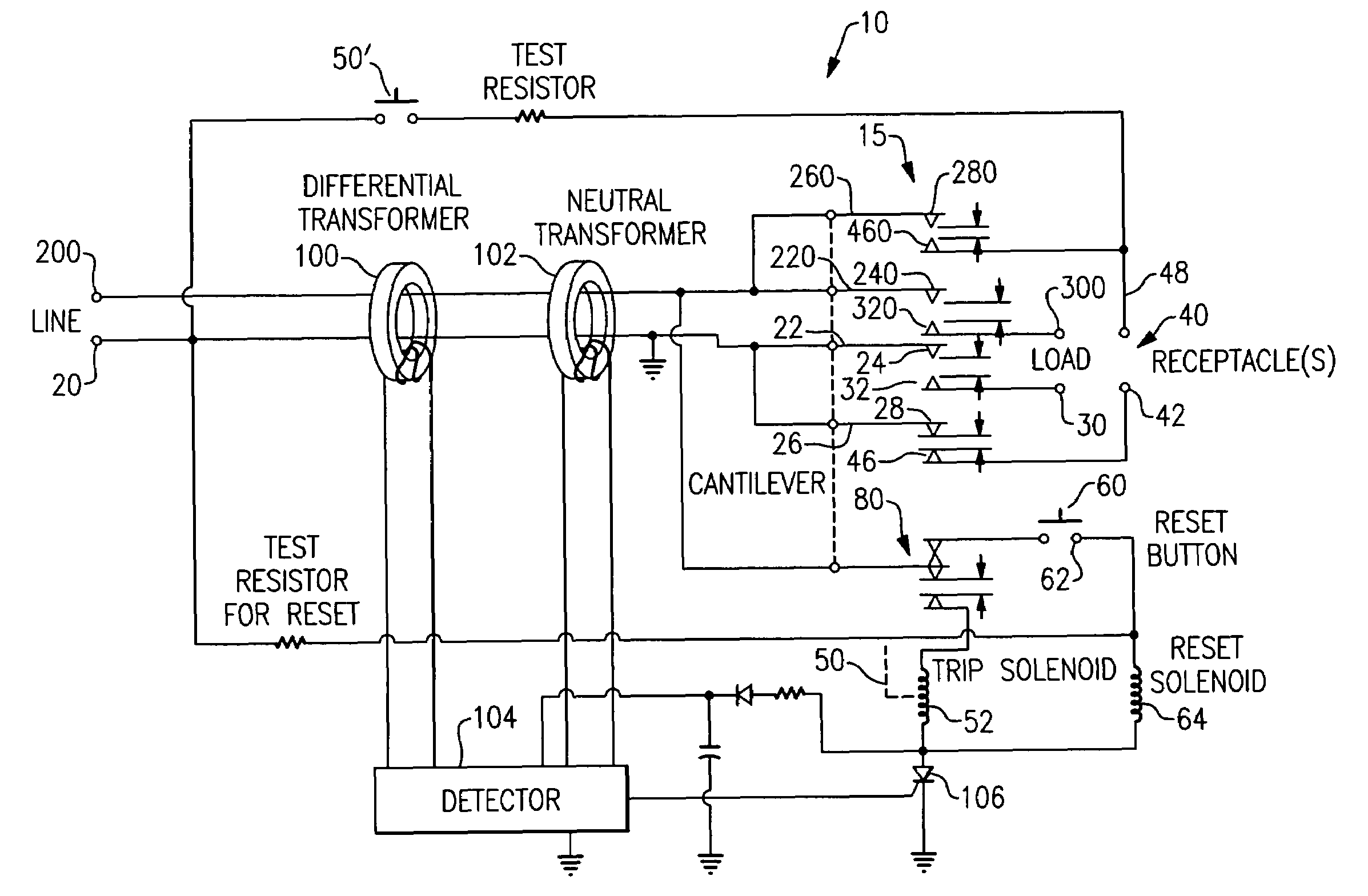
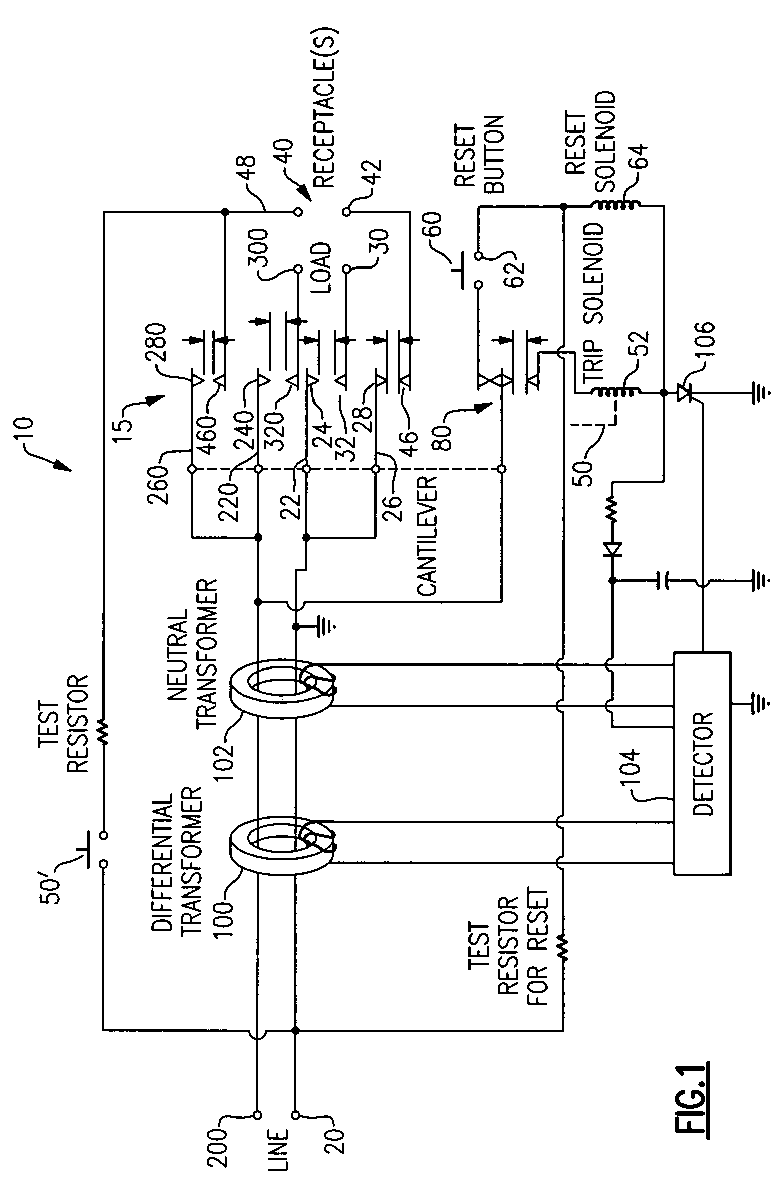
[0051]As embodied herein, and depicted in FIG. 1, a block diagram of an electrical wiring device 10 in accordance with the present invention is disclosed. While FIG. 1 includes a GFCI, the present invention is equally applicably to AFCIs and / or other protective devices. The wiring device 10 includes a tripping mechanism that includes ground fault sensor 100 and grounded neutral sensor 102 coupled to detector 104. Detector 104 is coupled to silicon controlled rectifier (SCR) 106. SCR 106 is turned on in response to a detection signal from detector 104. SCR 106, in turn, signals trip solenoid 52 to actuate a pivotal latch mechanism 80 to open the contacts in contact assembly 15.

[0052]With regard to contact assembly 15, neutral line terminal 20 is connected to cantilever member 22 and cantilever member 26. Cantilevers 22 and 26 are coupled to latch mechanism 80. Cantilever member 22 includes a moveable contact 24. In the reset position, moveable contact 24 is configured to mate with st...

second embodiment

[0076]As embodied herein and depicted in FIG. 8, a block diagram of an electrical wiring device 10 in accordance with the present invention is disclosed. Wiring device 10 is depicted as a GFCI. However, those skilled in the art will recognize that device 10 may be configured as an AFCI or another protective device. In this embodiment, a tri-contact design is employed. This design is also a four-pole design that is configured to deny power to the receptacles when the device is miswired and in a tripped state. Line neutral 20 is coupled to fixed neutral contact 500. Receptacle neutral contact 42 is coupled to fixed neutral contact 501. Neutral feed through terminal 30 is coupled to fixed load neutral contact 502. Each of the fixed contacts 500, 501 and 502 is paired with a moveable contact 505 disposed on tri-contact mechanism 506. On the “hot side,” each of the fixed contacts 508, 510 and 512 is paired with a moveable contact 514 disposed on tri-contact mechanism 516. The wiring devi...

fourth embodiment

[0107]FIG. 22 is a perspective view of an electrical wiring device in accordance with the present invention. In this embodiment the cantilevers may be oriented in any angular relationship one to the other, for example, at right angles as depicted in the Figure. As shown, line cantilever 816 is L-shaped to accommodate components disposed within device 10. Load cantilever 814 is similar to the cantilever structures previously shown. Thos skilled in the art will recognize that the arrangement may be reversed, with the load cantilever being L-shaped.

[0108]FIG. 23 is a schematic of the electrical wiring device depicted in FIG. 13. However, the schematic of FIG. 19 is applicable to all of the embodiments disclosed herein. The protective device of the present invention is configured to sense and detect fault conditions that may occur in the electrical distribution system, as well as simulated fault conditions, that are either manually or automatically generated. Fault conditions may includ...


PUM


Abstract

The present invention is directed to an electrical wiring device that includes a plurality of line terminals, a plurality of load terminals, and a set of receptacle load terminals. The device includes a fixed contact and a first cantilever member including a first contact disposed thereon. A second cantilever member is disposed between the fixed contact and the first cantilever. The second cantilever member includes a dual contact disposed thereon. The dual contact is disposed between the fixed contact and the first contact. An actuator is configured to move between a closed position and a tripped position. The actuator is configured to urge the first cantilever toward the second cantilever to close the fixed contact, the first contact, and the dual contact such that the plurality of line terminals, the plurality of load terminals, and the set of receptacle load terminals are electrically continuous in the closed position. The actuator is also configured to release the first cantilever from the second cantilever to open the fixed contact, the first contact, and the dual contact. The plurality of line terminals, the plurality of load terminals, and the set of receptacle load terminals are decoupled in the tripped position.

Description

CROSS-REFERENCE TO RELATED APPLICATIONS[0001]This is a continuation-in-part of co-pending U.S. Patent application Ser. No. 10 / 900,769 Protection Device with Power to Receptacle Cut-Off filed on Jul. 28, 2004, the content of which is relied upon and incorporated herein by reference in its entirety, and the benefit of priority under 35 U.S.C. § 120 is hereby claimed. U.S. patent application Ser. No. 10 / 900,769 claims priority under 35 U.S.C. §119(e) based on U.S. Provisional Patent Application Ser. No. 60 / 541,506, filed Feb. 3, 2004, the contents of which are relied upon and incorporated herein by reference in their entirety.BACKGROUND OF THE INVENTION[0002]1. Field of the Invention[0003]The present invention relates generally to protection devices, and particularly to protection devices having power to the receptacles cut-off features.[0004]2. Technical Background[0005]Most residential, commercial, or industrial buildings include one or more breaker panels that are configured to rece...

Claims


Application Information

Patent Timeline
Patent Type & Authority Patents(United States)
IPC IPC(8): H02H3/00
CPCH01H83/04H01H2071/044
Inventor WEEKS, RICHARDMORGAN, KENT
Owner PASS SEYMOUR
Why Eureka
Try Eureka