Sliding ruler square

Inactive Publication Date: 2007-02-13
MARSHALL GEORGE THOMAS
View PDF8 Cites 15 Cited by
  • Summary
  • Abstract
  • Description
  • Claims
  • Application Information

AI Technical Summary

Problems solved by technology

The many features of the new square in combination therefore substantially obviates the necessity for multiple tools, repositioning the tool relative to the typical work piece and other limitations and disadvantages of the related art.

Method used


Image

  • Sliding ruler square
  • Sliding ruler square
  • Sliding ruler square

Examples


Embodiment Construction

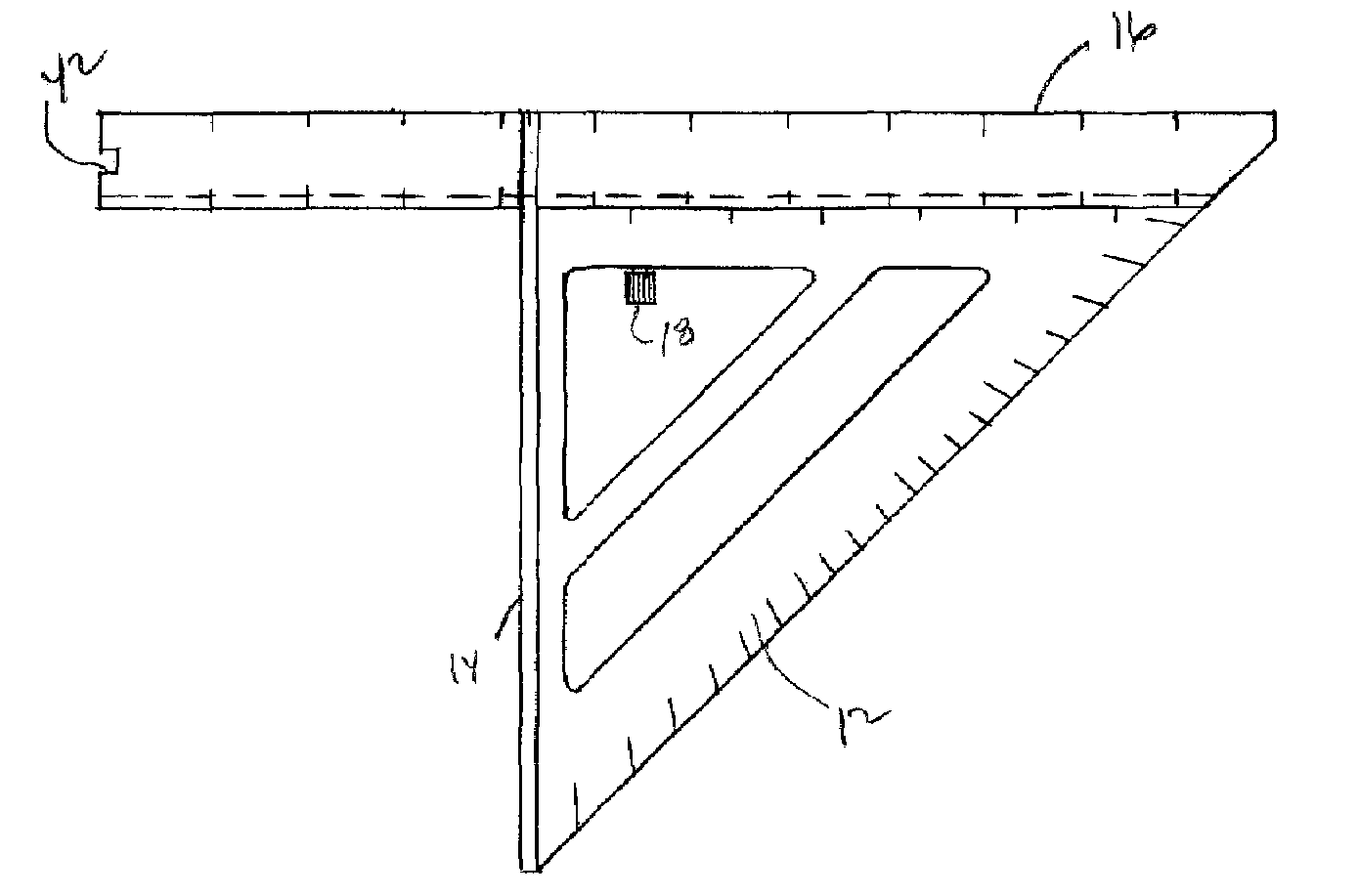
[0025]Although particular embodiments of the invention have been described in detail for purposes of illustration, various modifications may be made without departing from the spirit and scope of the invention. Accordingly, the invention is not to be limited except as by the appended claims. Referring now in greater detail to the various figures of the drawings wherein like reference characters refer to like parts, there is shown at 10 in FIG. 1, a new type of square used in the construction industry for assisting the marking and scribing of cut lines at pre-selected offset angles on a work piece.

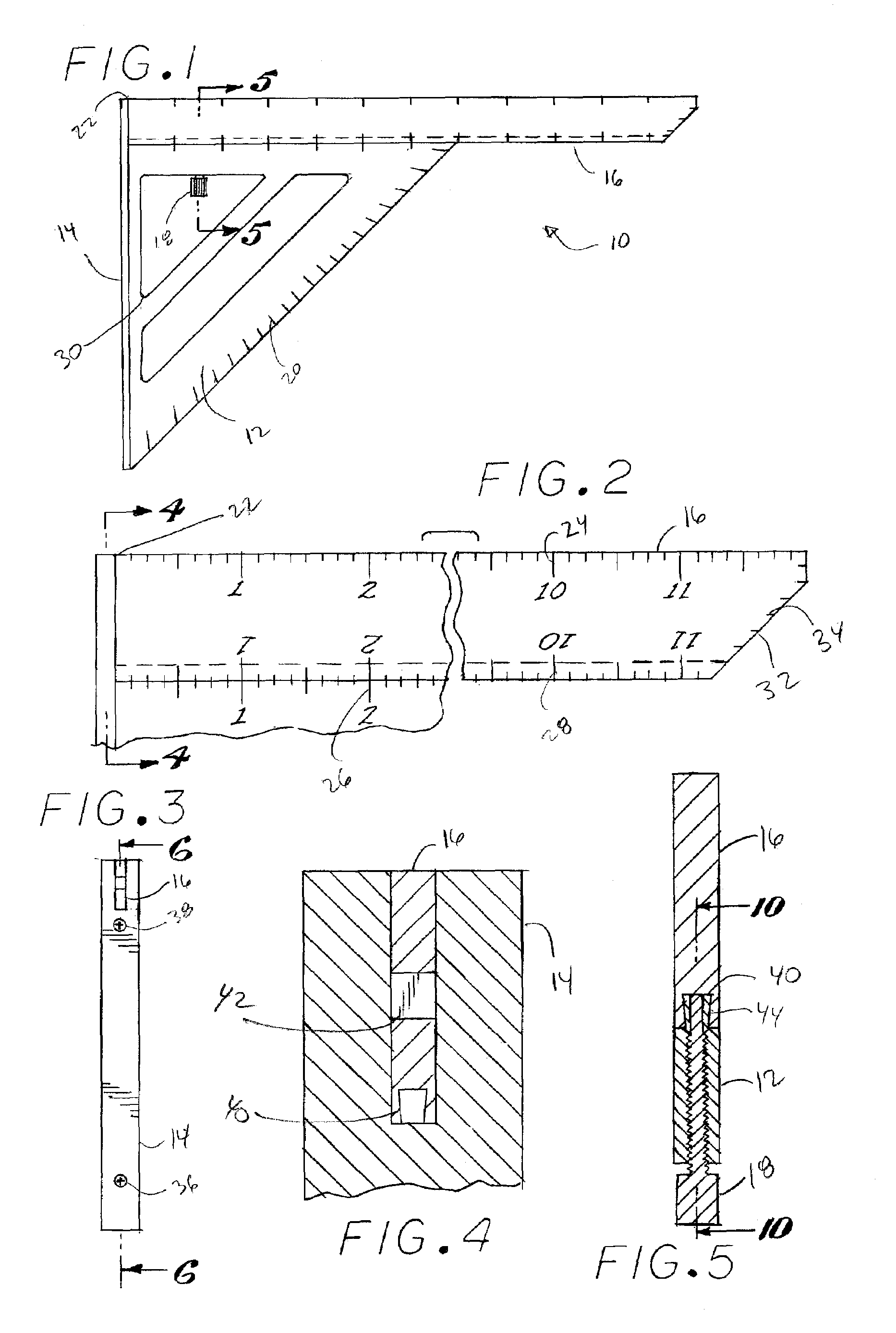
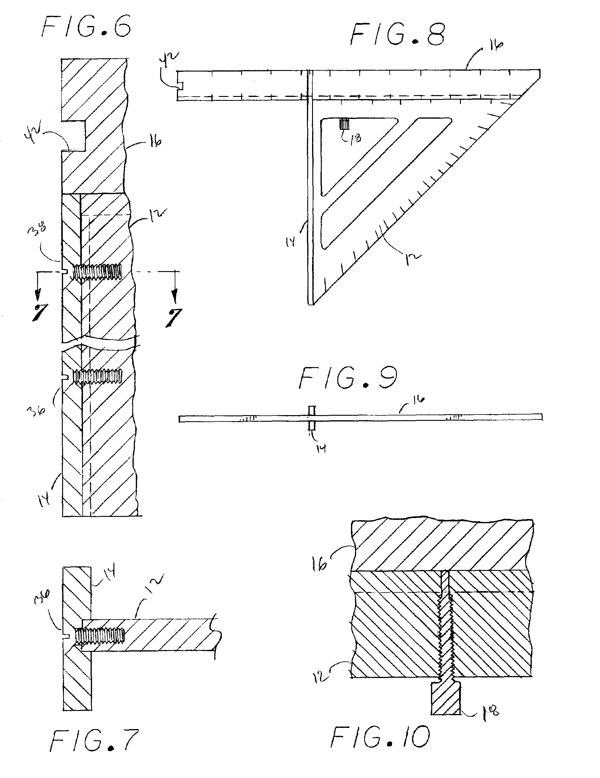
[0026]Referring to FIG. 1, showing the ruler square according to the present invention, the ruler square is generally comprised of a base 12 being of a right triangular shape have a left edge, a top edge and a hypotenuse edge, a fence 14 element fixed to and integral to the base extending along the left base edge of the triangular base and an extendible straightedge element 16 movably attac...


PUM


Abstract

The present invention is a sliding ruler square that provides an adjustable and extendible straightedge element permitting a user to conveniently scribe lengthy cut lines at pre-selected angles across a work piece typically utilized in the construction industry without the necessity as exhibited by the prior art to reposition the tool. The inventions comprises a right triangularly shaped base with a fence on one base edge, a sliding straightedge on the other base edge and markings along the straightedge and the hypotenuse and other edges of the base to present a variety of ways to measure and mark. The tool combines a number of measurement and scribing functions typically requiring several tools.

Description

FIELD OF THE INVENTION[0001]The present invention relates to the field of hand square tools. More particularly, this invention is directed to a square with unique features presented by an extendible measurement straightedge element.BACKGROUND OF INVENTION[0002]Hand squares are well known in the construction industry being used to measure, mark and cut construction materials. Cutting materials in the building industry typically requires the measuring and marking of a work piece at pre-selected angles relative to a dimension of the work piece for purposes of fitting into structures. A variety of hand squares are known that are specialized for a particular measuring and marking functions.[0003]For example, the combination square is typically used to measure and mark a cut line perpendicular to the edge of a plank. Framing squares are used for measuring and marking rafters or stringers. Layout squares are used for joists and studs.[0004]The triangular square, also commonly known as a sp...

Claims


Application Information

Patent Timeline
Patent Type & Authority Patents(United States)
IPC IPC(8): B43L7/027
CPCB43L7/005B43L7/0275G01B3/566G01B3/04B43L7/14
Inventor MARSHALL, GEORGE THOMAS
Owner MARSHALL GEORGE THOMAS
Why Eureka
Try Eureka