Optical recording method for high transfer rates

a recording method and transfer rate technology, applied in the field of optical recording media recording at a high transfer rate, can solve the problems of large jitter in the playback signal, the inability to strictly conform to the write waveform, and the time width of the individual pulses that make up the pulse train becomes extremely short, and achieves the effect of high transfer ra

Inactive Publication Date: 2007-02-13
TDK CORPARATION
View PDF15 Cites 0 Cited by
  • Summary
  • Abstract
  • Description
  • Claims
  • Application Information

AI Technical Summary

Benefits of technology

[0008]Another object of the present invention is to provide an optical recording method that can accurately achieve the desired write waveform.

Problems solved by technology

Moreover, when laser beam is modulated into pulse trains and irradiated, the time width of the individual pulses that make up the pulse train becomes extremely short.
To wit, laser beam emission that strictly conforms to the write waveform cannot be obtained.
As a result, the heating of the recording layer is inadequate so the recording marks may be warped in shape or too small, and as a result, jitter in the playback signal may become large or the playback amplitude may become lower.

Method used


Image

  • Optical recording method for high transfer rates
  • Optical recording method for high transfer rates
  • Optical recording method for high transfer rates

Examples


examples

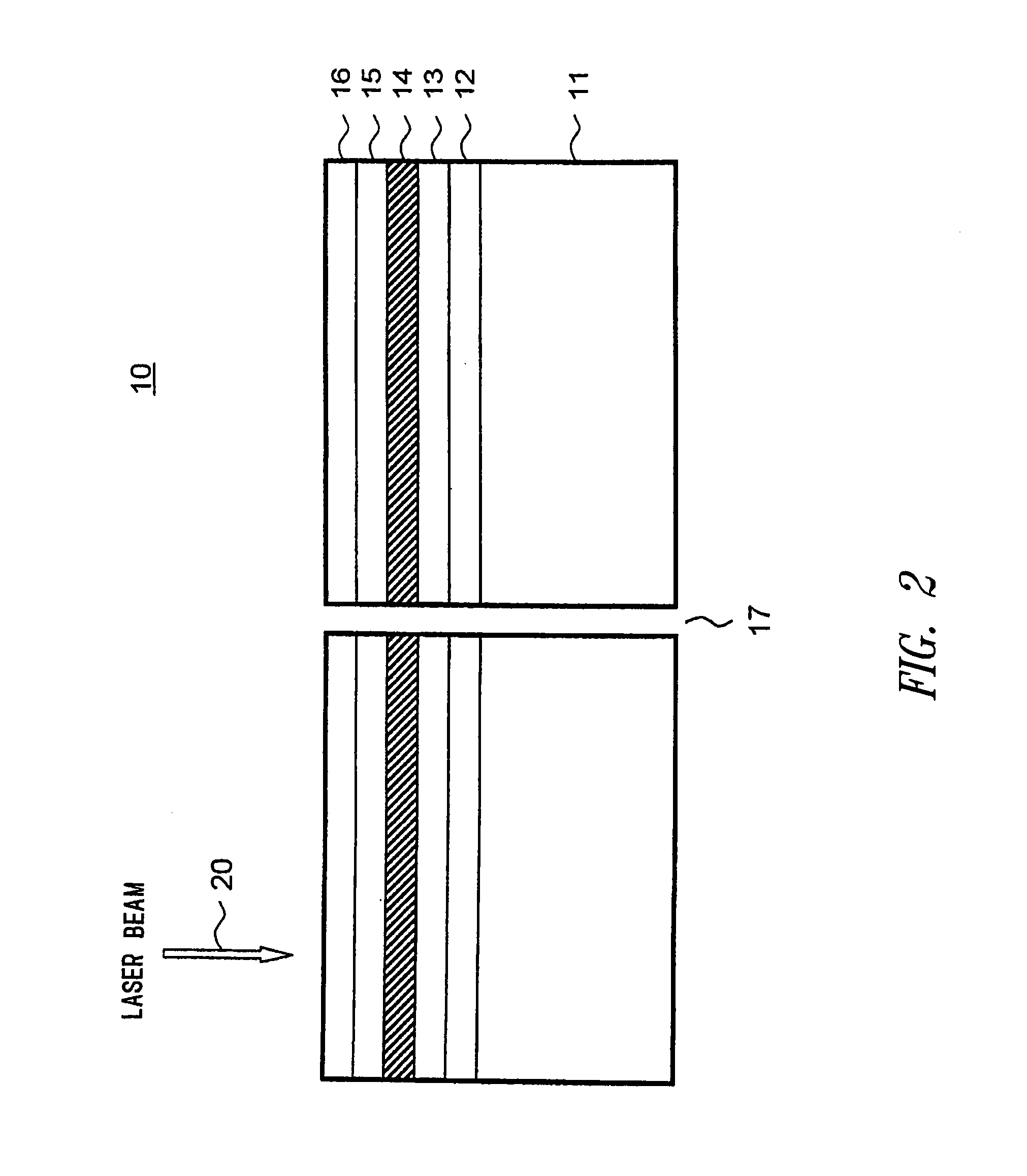
[0101]A sample optical recording disc was manufactured by preparing a disc-shaped polycarbonate substrate 120 mm in diameter and 1.2 mm thick with the groove formed simultaneously by injection molding, and forming on its surface a reflective layer, second dielectric layer, recording layer, first dielectric layer and transparent cover layer by the procedure given below.

[0102]The reflective layer has a thickness of 100 nm and was formed by sputtering in an argon (Ar) atmosphere using Ag98Pd1Cu1 as the target. The second dielectric layer has a thickness of 20 nm and was formed by sputtering in an Ar atmosphere using Al2O3 as the target. The recording layer has a thickness of 12 nm and was formed by sputtering in an Ar atmosphere. The composition of the recording layer is:

[0103]Ag0.5In0.5Sb76Te17Ge6

[0104]on an atom ratio. The first dielectric layer has a thickness of 130 nm and was formed by sputtering in an Ar atmosphere using ZnS (85 mol %)-SiO2 (15 mol %) as the target. The transpar...


PUM

PropertyMeasurementUnit
thicknessaaaaaaaaaa
thicknessaaaaaaaaaa
thicknessaaaaaaaaaa

Abstract

An optical recording method that performs recording by irradiating optical recording media with laser beam modulated in intensity based on a write waveform is provided. The write waveform has a plurality of write pulse blocks for forming write marks, and each write pulse block has at least one type of upward pulse. In the event that the width of said upward pulse is so narrow that the laser beam intensity corresponding to the peak intensity of that upward pulse cannot be obtained, the peak intensity of that upward pulse is increased so that, in said laser beam, the beam intensity it should have or a value close thereto is obtained. Thereby, good recording and playback characteristics can be obtained even when recording at a high transfer rate.

Description

BACKGROUND OF THE INVENTION[0001]The present invention relates to a method of recording on optical recording media at a high transfer rate.DESCRIPTION OF THE PRIOR ART[0002]Optical recording media that permits high-density recording and also permits the recorded information to be erased and rewritten have been attracting attention in recent years. Among rewritable optical storage media, the phase-change technology involves irradiating the media with at least a laser beam to change the crystal state of the recording layer to perform recording and detecting the change in the crystalline state of the recording layer accompanying this state change to perform playback. Phase-change type optical recording media is attracting attention because the optical system of the drive is simpler than that for magneto-optical recording media.[0003]When recording information onto phase-change type optical recording media, the recording layer is irradiated with a high-power (write power) laser until it...

Claims


Application Information

Patent Timeline
Patent Type & Authority Patents(United States)
IPC IPC(8): G11B7/0045G11B20/10G11B7/00G11B7/006G11B7/125
CPCG11B20/10G11B7/0062G11B7/0045
Inventor KATO, TATSUYAUTSUNOMIYA, HAJIMEHIRATA, HIDEKI
Owner TDK CORPARATION
Why Eureka
Try Eureka