System and method for generating and measuring noise parameters

a technology of noise parameters and noise figures, applied in the direction of noise figures or signal-to-noise ratio measurement, instruments, transmission monitoring, etc., can solve the problems of less complex and reliable noise testing equipment, and achieve the effect of accurately measuring noise parameters, eliminating or greatly reducing disadvantages and problems associated

Active Publication Date: 2007-02-13
TEXAS INSTR INC
View PDF5 Cites 4 Cited by
  • Summary
  • Abstract
  • Description
  • Claims
  • Application Information

AI Technical Summary

Benefits of technology

[0003]From the foregoing it may be appreciated by those skilled in the art that a need has arisen for a system for accurately measuring the noise parameters. In accordance with the present invention, a system and method for measuring noise parameters is provided that substantially eliminates or greatly reduces disadvantages and problems associated with conventional testing equipment.
[0005]Depending on the specific features implemented, particular embodiments of the present invention may exhibit some, none, or all of the following technical advantages. Various embodiments may be capable of generating white Gaussian noise for testing electronic components. Specifically, an arbitrary wave generator may be used to generate white noise that may be modulated. Some embodiments may be capable of generating a white noise signal of a lower voltage standing wave ratio. Accordingly, the accuracy of the resulting noise figure measurement may be improved. Other embodiments may be capable of generating noise signals of different excess noise ratios. Thus, a single noise source may be used to test a variety of different devices.
[0006]Other embodiments may be capable of attenuating the noise signal to compensate for signal path loss or device noise to achieve a more accurate noise figure measurement. Additionally, some embodiments may eliminate the need for switches and other hardware in the noise testing equipment. Thus, the noise testing equipment may be less complex and more reliable.

Problems solved by technology

Thus, the noise testing equipment may be less complex and more reliable.

Method used


Image

  • System and method for generating and measuring noise parameters
  • System and method for generating and measuring noise parameters

Examples


Embodiment Construction

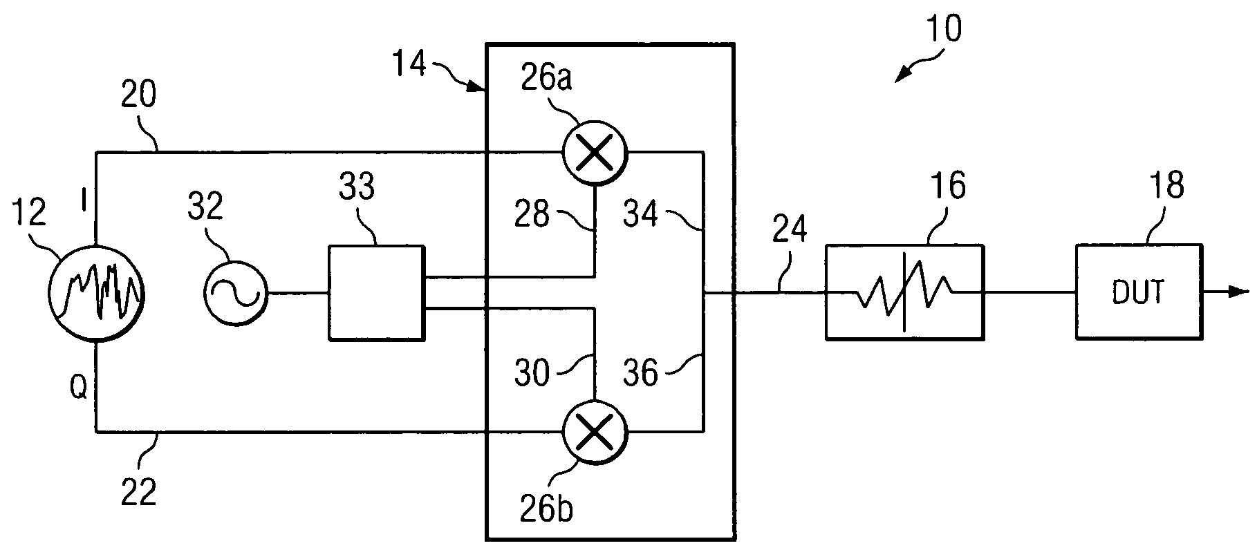
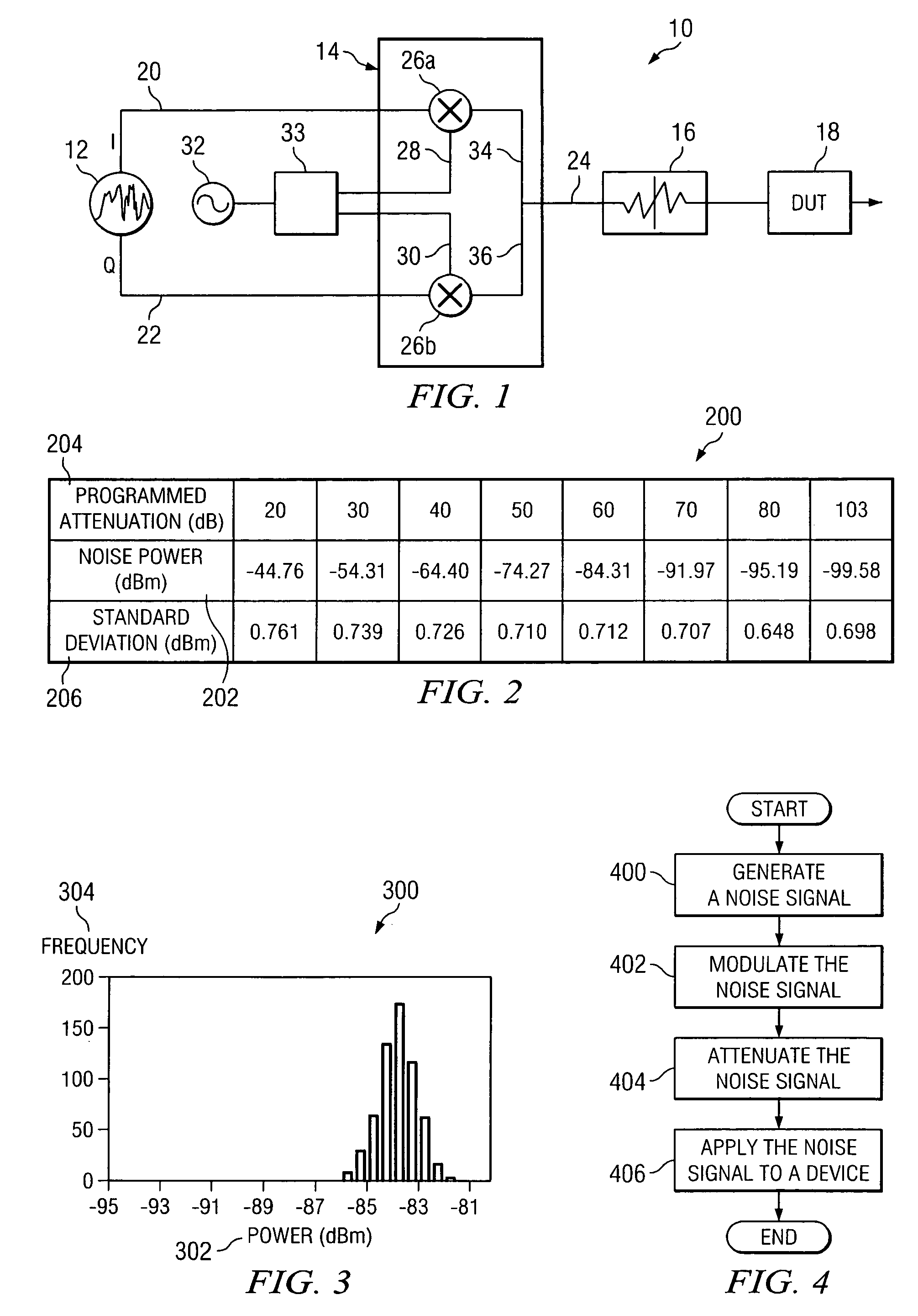
[0013]FIG. 1 is a block diagram of a noise testing system 10 that may be used to test RF / microwave devices in accordance with one embodiment of the present invention. Noise testing system 10 includes a noise source 12, a modulator 14, and an attenuator 16. Noise testing system 10 may be used to generate white Gaussian noise for the noise parameter testing of a DUT 18. The accuracy of noise testing equipment is particularly important for DUTs 18 that are intended to operate at RF / microwave frequencies. Such DUTs 18 may include the components of wireless devices in the cellular telephone industry, which are typically designed to operate in a frequency range on the order of approximately 10 MHz to 6 GHz. Thus, in particular embodiments, DUT 18 may include a global systems for mobile (GSM) transceiver, a global positioning system (GPS), a Bluetooth receiver, or other cellular component. Because the noise signal generated by noise testing system 10 is modulated and attenuated to a desire...


PUM


Abstract

A method for measuring noise parameters includes generating a noise signal at a noise source. The noise signal includes a first input signal at a first frequency and a second input signal at a second frequency. The first input signal and the second input signal are modulated onto a carrier to generate a modulated signal. The modulated signal is attenuated to a desired power level and applied to a device under test to obtain a noise measurement.

Description

TECHNICAL FIELD OF THE INVENTION[0001]This invention relates in general to the testing of electronic components, and more particularly to the generation and measurement of noise parameters in an electronic component.BACKGROUND OF THE INVENTION[0002]Testing equipment may be used to accurately generate and measure the noise parameters of a device under test (DUT). The noise parameters of a component are usually specified in terms of a noise factor F. The noise factor of a device is defined as the ratio of the signal-to-noise ratio available from the DUT output to the signal-to-noise ratio of the DUT input, at a standard reference temperature of 290 degrees Kelvin. Noise factor is often expressed in dB, which is sometimes referred to as a noise figure. Noise figure testing equipment typically includes a noise source that is cycled on and off to provide two power levels. The noise source results in a noise signal that must be matched to the DUT as closely as possible. Typical noise sour...

Claims


Application Information

Patent Timeline
Patent Type & Authority Patents(United States)
IPC IPC(8): G01R25/00G06F15/00H04B17/00
CPCH04B17/345
Inventor LARGEY, HENRY P.HEATON, DALE A.ZANG, LIANRUI
Owner TEXAS INSTR INC
Why Eureka
Try Eureka