
Connection between a steering mechanism and a steering column of a motor vehicle steering system

Inactive Publication Date: 2007-02-20
MAGNA STEYR FAHRZEUGTECHN
View PDF13 Cites 22 Cited by
  • Summary
  • Abstract
  • Description
  • Claims
  • Application Information

AI Technical Summary

Benefits of technology

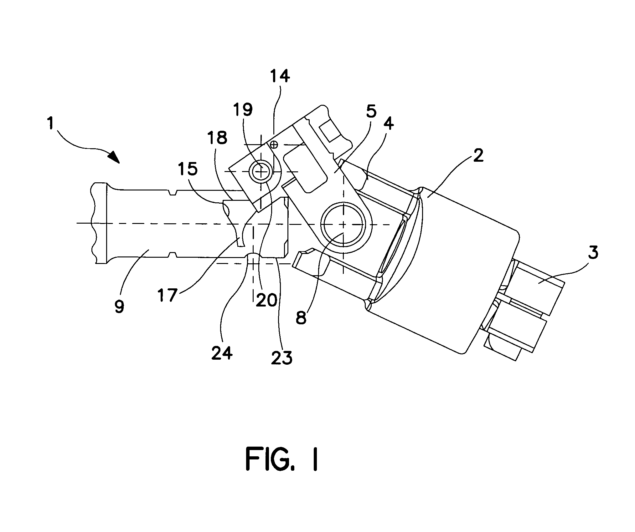
[0005]Owing to the design of a bolt, on the one hand, and of a groove, on the other hand, on the connecting partners of coupling piece and steering column or steering mechanism, and owing to the special configuration of the groove profile, the connecting partners are moved, during the pivoting of the coupling piece after the bolt has engaged in the groove, relative to each other in a restricted guide means and are automatically aligned axially to each other. A prerequisite is, of course, that one of the two connecting partners can be adjusted axially, so that it can be aligned on account of being able to move axially. Furthermore, the entry opening of the groove has to be large enough in order to be able to easily accommodate the bolt even if there are relatively large axial deviations from the desired relative connecting position of the connecting partners. By means of the profile according to the invention of the end section of the groove, the bolt obtains an axially immovable support on the other connecting partner, which is designed with the groove. It is therefore possible with the invention to carry out the installation without particular effort and rapidly with one hand, even in the case of small structural spaces and poor accessibility for manual installation, since the correct relative position of the connecting partners in the connecting position is always obtained by virtue of the automatic alignment. This enables the clamping screw to be screwed into the thread through the opposite openings in clamping jaws of the coupling part without impediment. Incorrect rotational positions of the steering column or coupling pieces which have not been opened out correctly are immediately recognized owing to the special geometry of the groove, which means that incorrect installations can be prevented from the outset.

Problems solved by technology

However, in the known device, the steering column and coupling element have to be exactly aligned with each other axially, since otherwise the locking bolt and the clamping screw come to lie next to the tapering and, as a result, firstly the locking bolt loses its locking function and, secondly, the clamping screw cannot be placed through the holes.
This requires an increased effort in terms of adjustment which can only be carried out with both hands.

Method used


Image

  • Connection between a steering mechanism and a steering column of a motor vehicle steering system
  • Connection between a steering mechanism and a steering column of a motor vehicle steering system
  • Connection between a steering mechanism and a steering column of a motor vehicle steering system

Examples


Embodiment Construction

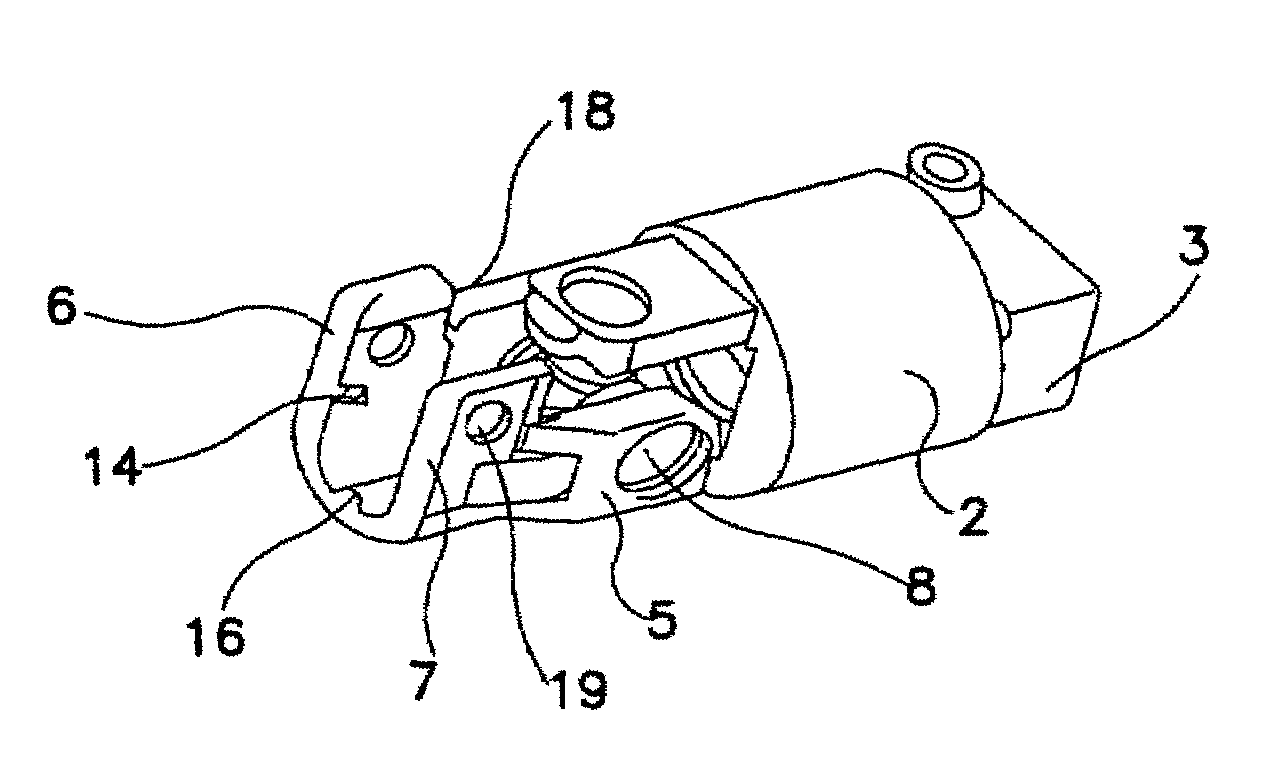
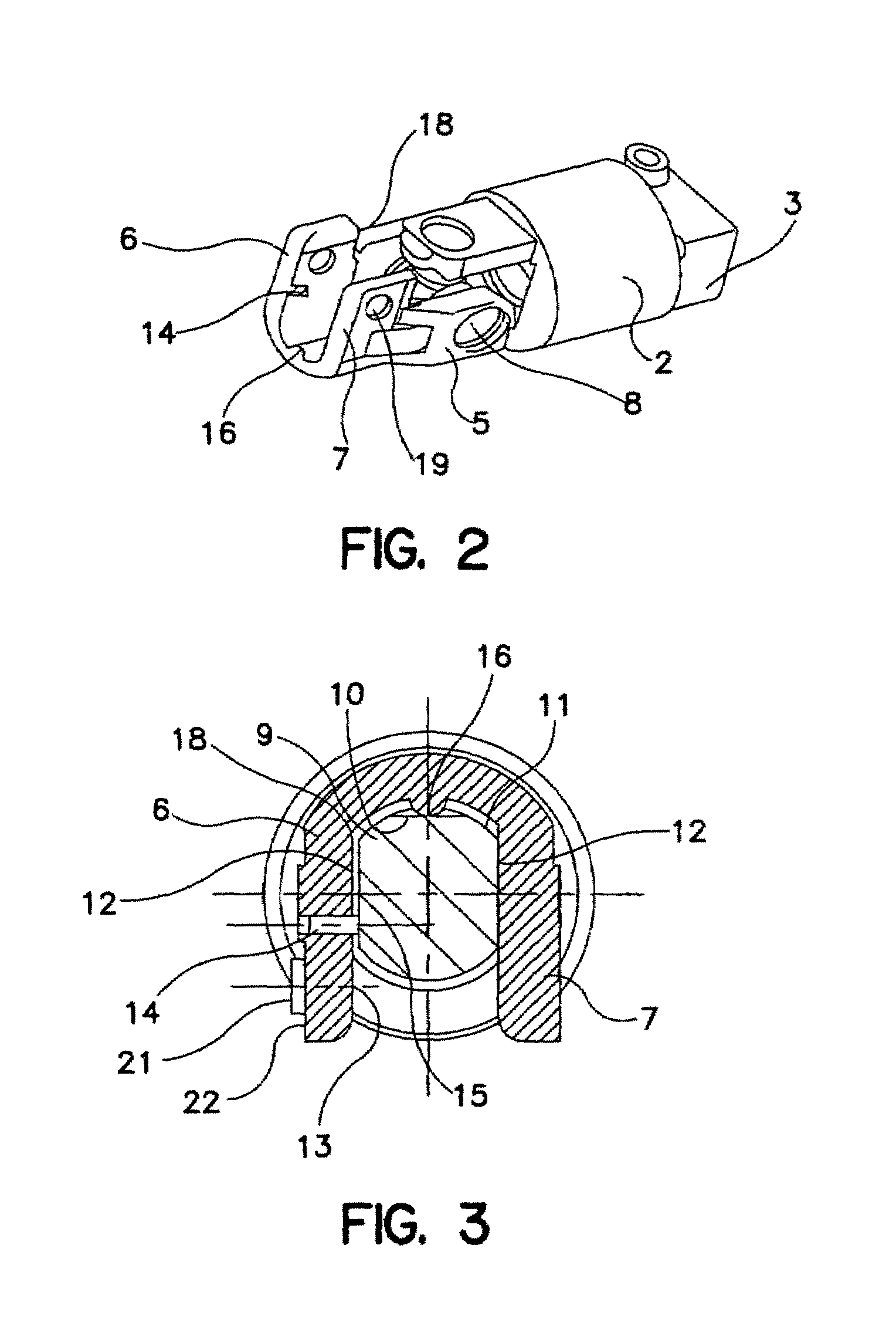
[0010]FIG. 1 illustrates a connection between a steering column 1 of a motor vehicle and a steering mechanism. These two components, the steering column 1 and steering mechanism, are connected by a steering coupling 2 which is fastened at one end 3 to the steering mechanism and, at the other end 4, bears a coupling piece 5 in an articulated manner. As an alternative, it is also conceivable to fix the steering coupling 2 by the end 3 rigidly to the steering column 1, so that the connection is produced in a reverse sequence to the exemplary embodiment described. The coupling piece 5 and the component to which the steering coupling 2 is not fixed after the pre-installation process, this therefore being the steering column 1 in the first case, and to which the coupling piece 5 is to be connected, form connecting partners.

[0011]The coupling piece 5 has two clamping jaws 6, 7 which lie opposite each other and which, after the coupling piece 5 has been pivoted about the axis of articulatio...


PUM


Abstract

The invention relates to a connection between a steering mechanism and a steering column (1) of a motor vehicle steering system. The connection comprises a steering coupling (2) which connects these two components, is attached by one end (3) to the steering mechanism or to the steering column (1) and, at the other end (4), bears a coupling piece (5) in an articulated manner. The latter forms a connecting partner with the other component (1) in each case and has two clamping jaws (6, 7) which, after the coupling piece (5) has been pivoted around the axis of articulation (8), engage around a section (9) of the other component (1).

Description

BACKGROUND OF THE INVENTION[0001]The invention relates to a connection between a steering mechanism and a steering column of a motor vehicle steering system.[0002]A connection according to the generic type is disclosed in EP 044 591 B1. In order to produce the connection in this case, a coupling piece which is arranged pivotably on a steering column and has two clamping jaws is pivoted via a shaft journal of a steering mechanism fixed in a motor vehicle. The coupling piece is equipped between its clamping jaws with a spring-loaded locking device, the locking bolt of which is pressed into an unlocking position by the shaft journal during the pivoting movement. After the pivoting movement has finished and therefore when the upper side of the shaft journal bears against the base of the U shape of the coupling piece, the locking bolt, which is no longer covered by the shaft journal in this position, is released, so that the locking bolt, driven by the spring force exerted on it, dips be...

Claims


Application Information

Patent Timeline
IPC IPC(8): F16D3/00B62D1/20F16D1/08F16D3/38
CPCB62D1/20F16D1/0864F16D3/382Y10T403/32008Y10T403/32041
Inventor STIMPFL, MARKUSKOLLER, ERWINBRAUTIGAM, WOLFGANG
Owner MAGNA STEYR FAHRZEUGTECHN
Learn More