Tool with deployable cutting blade

a cutting blade and tool technology, applied in the field of tools, can solve the problems of increasing the stress of the substrate, reducing the service life of the tool,

Inactive Publication Date: 2007-02-20
STOUT MEDICAL GROUP
View PDF14 Cites 85 Cited by
  • Summary
  • Abstract
  • Description
  • Claims
  • Application Information

AI Technical Summary

Benefits of technology

[0012]In a further example, the moving means comprises a flexible resilient beam having a first end mounted within the chamber and an opposite end. The beam is oriented substantially lengthwise along the bit shaft. The chamber has a sidewall, and the cutting blade is mounted on the opposite end of the beam and adjacent to the sidewall. The beam is biased to normally position the cutting blade in the extended position, the blade being held in the extended position by contact with the substrate upon rotation of the bit shaft in a direction tending to force the cutting blade against the sidewall. The cutting blade is resiliently deflected into the chamber by contact with the substrate upon rotation of the bit shaft in an opposite direction.

Problems solved by technology

When used in bone matter, conventional fasteners, such as screws, fail at relatively low loads because the screw distributes the load only to a small area of the substrate immediately around the screw, resulting in high stresses in the substrate.
Fastener loads in bone matter are also limited by the composition of the bone matter, which comprises a relatively hard cortical layer surrounding an inner cancellous layer of relatively soft tissue.
The cancellous layer is largely ineffective at retaining the fastener, thus concentrating the load from the fastener entirely in the hard cortical tissue and raising the stress even further.
Such tools tend to be complicated and require an extra step in that a pilot hole must first be drilled into the substrate and then the tool employed to carve out the undercut in the otherwise inaccessible interior or back face.

Method used


Image

  • Tool with deployable cutting blade
  • Tool with deployable cutting blade
  • Tool with deployable cutting blade

Examples


embodiment 10

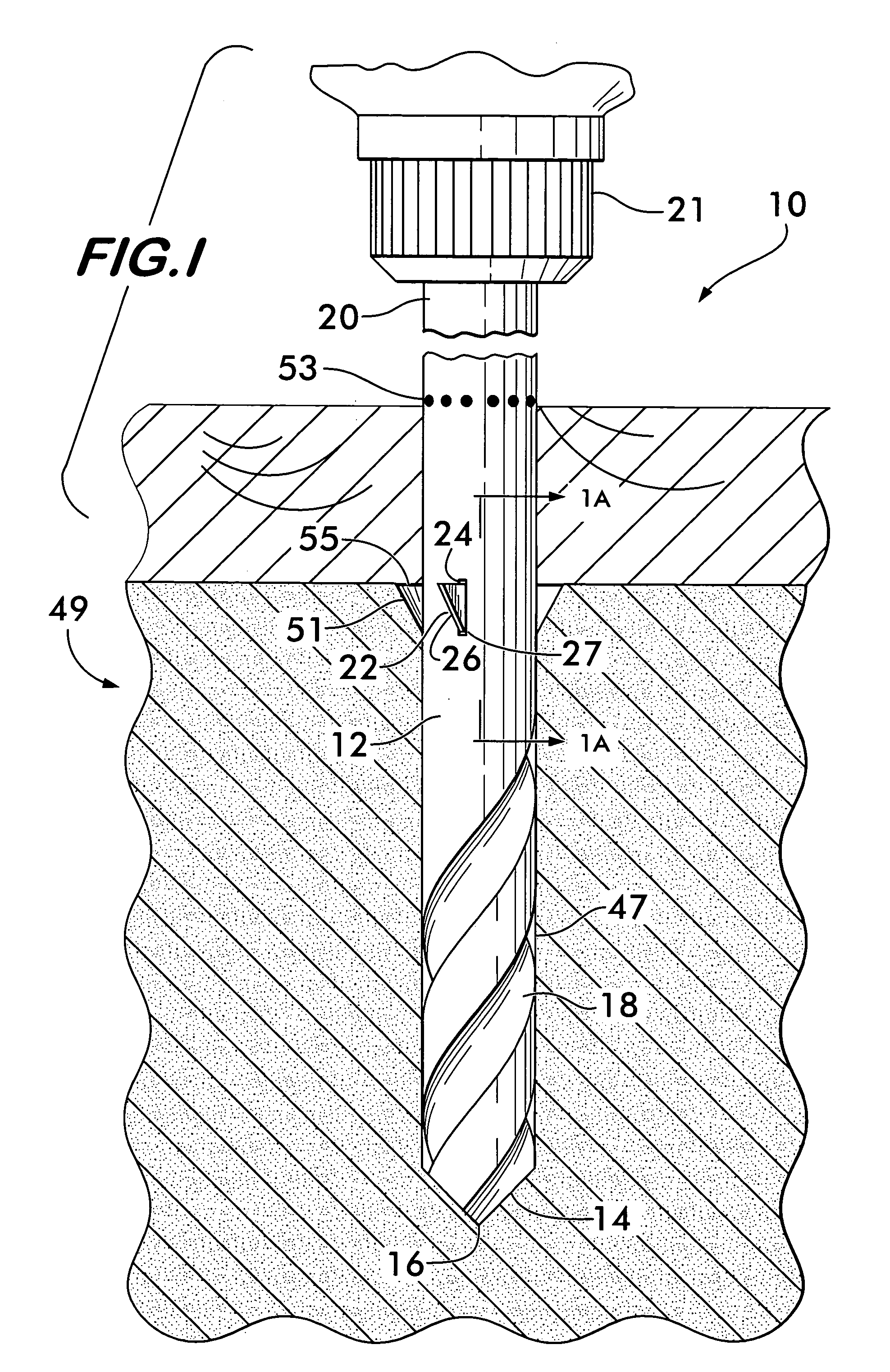
[0023]FIG. 1 shows an embodiment 10 of a tool with a deployable cutting blade for making an undercut according to the invention. Tool 10 comprises an elongated bit shaft 12 having opposed angularly oriented cutting edges 14 arranged at a cutting tip 16. Helical grooves 18 extend longitudinally along the bit shaft 12 to facilitate removal of cutting debris generated by the cutting edges 14. A tang 20 is positioned at the opposite end of the bit shaft 12. The tang is preferably cylindrical but may have other shapes compatible with a particular chuck 21 in order to prevent slippage of the bit relative to the chuck during drilling.

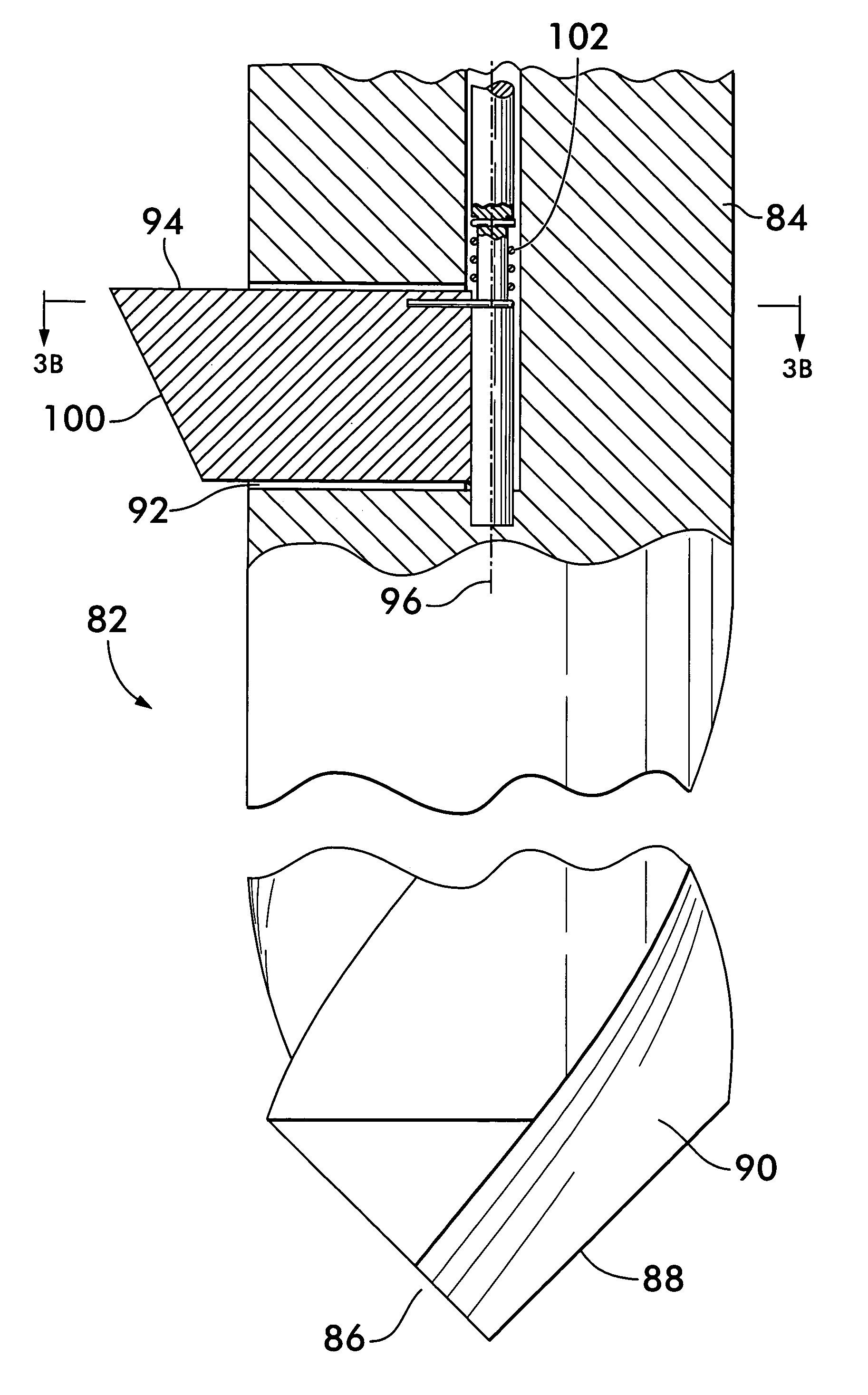
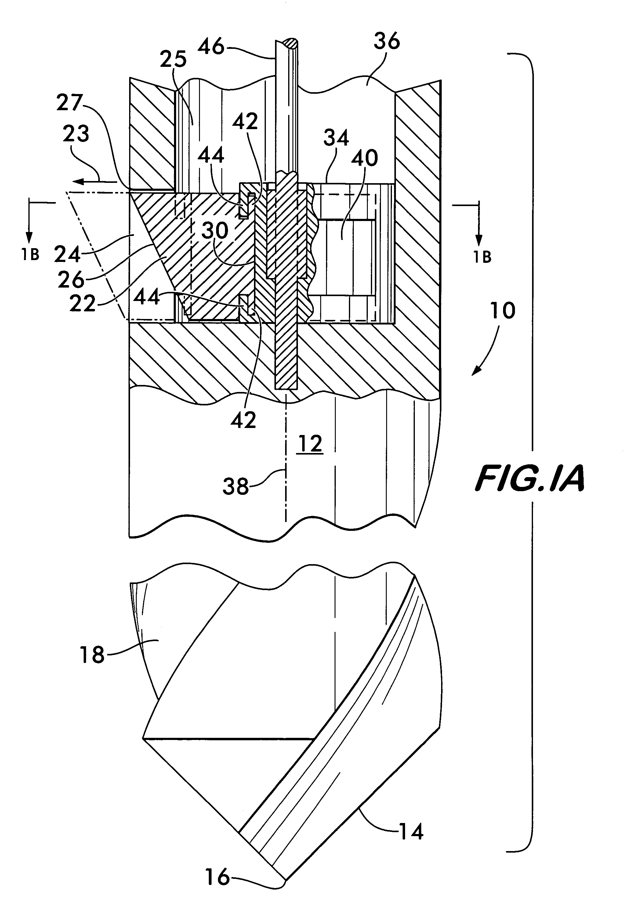
[0024]A cutting blade 22 is slidably positioned within a slot 24 positioned within the bit shaft 12 in spaced relation to the cutting tip 16. As shown by arrow 23 in FIG. 1A, blade 22 is movable radially relatively to the bit shaft 12 within the slot 24 between a retracted position, shown in solid line with the blade 22 located within a chamber 25 in the bit s...

embodiment 50

[0030]FIGS. 2A and 2B show another embodiment 50 of a tool with a deployable cutting blade according to the invention. Tool 50 has a bit shaft 52 with angled cutting edges 54 at its cutting end 56 and a tang (not shown) at its opposite end. Helical grooves 58 extend along the surface 60 of the bit shaft. A longitudinal bore 62 is positioned, preferably coaxially, within bit shaft 52. Bore 62 is in communication with a chamber comprising a passageway 64 oriented at an angle 66 relatively to the bore 62. Passageway 64 leads to an opening 67 in the surface 60 of the bit shaft 52, the opening 67 being in spaced relation to cutting edges 54. Passageway 64 comprises an upper guide surface 68 and a lower guide surface 70. The guide surfaces are preferably curved for reasons described below.

[0031]A cutting blade 72 is moveably positioned within passageway 64. Blade 72 comprises a flexible and resilient blade shaft 74 which is deflected into a curved shape as it engages the guide surfaces 68...

embodiment 104

[0037]FIGS. 4A and 4B illustrate another embodiment 104 of a tool according to the invention. Again, tool 104 has a bit shaft 106 comprising a cutting end with angled cutting edges 108 and a tang (not shown) at the opposite end for engaging a chuck of a drill. Helical grooves 112 extend along the bit shaft 106 for debris removal during drilling.

[0038]A longitudinal bore 114 extends from the tang along bit shaft 106, preferably coaxial therewith. The bore 114 is adapted to receive a passageway 115 conveying pressurized fluid, preferably supplied through a coupling (not shown) at the tang. The coupling is designed to pass the hydraulic fluid from a stationary source to the passageway 115 which rotates with the bit 104 during drilling.

[0039]A chamber 116 is positioned in the bit shaft 106 in spaced relation to the cutting edges 108. A cutting blade 118 is pivotally mounted within the chamber 116 and rotates about a pivot axle 120 oriented transversely to the bit shaft 106. Blade 118 ro...


PUM

PropertyMeasurementUnit
lengthaaaaaaaaaa
rotationaaaaaaaaaa
dimensionsaaaaaaaaaa

Abstract

A tool having a deployable cutting blade for making an undercut in a substrate is disclosed. The tool has a chamber positioned between its cutting tip and its tang. The cutting blade is movably mounted within the chamber. The blade is movable by sliding, pivoting or deflecting on a cantilever mounting and is movable between a retracted position within the chamber and an extended position projecting outwardly to engage and cut the substrate. Actuators for moving the blade include an eccentric cam mounted on a camshaft, a push rod and an inflatable balloon. Blades are also resiliently mounted and oriented so that their engagement with the substrate will cause them to retract into the chamber when the tool rotates in one direction and deploy into the extended position when the tool rotates in the opposite direction.

Description

FIELD OF THE INVENTION[0001]The invention concerns tools having a cutting tip and a cutting blade which may be deployed to make an undercut while drilling a hole in a substrate.BACKGROUND OF THE INVENTION[0002]It is often desirable to create a cavity or undercut in an inaccessible portion of a substrate, such as a back face or between the opposite faces of the substrate, the undercut having dimensions larger than the hole drilled into the substrate. Such undercuts are especially useful to attach fastening devices to brittle or low strength substrates because they allow the use of expanding anchoring devices which can spread the load over a greater area of the substrate, thereby lowering the stress and increasing the pull-out strength of the fastener.[0003]Bone matter is one example of a substrate in which expanding anchors may be used to good effect. When used in bone matter, conventional fasteners, such as screws, fail at relatively low loads because the screw distributes the load ...

Claims


Application Information

Patent Timeline
Patent Type & Authority Patents(United States)
IPC IPC(8): B23B51/00B23B51/02
CPCB23B51/0018B23B51/0036B23B51/02B23B51/0045Y10T408/906
Inventor GREENHALGH, E. SKOTT
Owner STOUT MEDICAL GROUP
Why Eureka
Try Eureka