
Distributed stereo system

a stereo system and distribution system technology, applied in the direction of stereophonic circuit arrangement, loudspeaker spatial/constructional arrangement, transmission, etc., can solve the problems of attenuator not increasing the output of amplifier, attenuator can only reduce the volume below the level, etc., to reduce speaker cable loss, increase the total system damping factor, and decentralise amplification

Inactive Publication Date: 2007-02-20
LEISURETECH ELECTRONICS
View PDF27 Cites 84 Cited by
  • Summary
  • Abstract
  • Description
  • Claims
  • Application Information

AI Technical Summary

Benefits of technology

"The invention is a distributed stereo audio system that allows for decentralized amplification and increased system damping factor. The system includes speakers, a source of stereo audio signals, a stereo amplifier, and a mains-operated electrical power supply. The amplifier is located in the same room as the speakers and is connected to the source of audio signals through a category 5 cable. The cable is simple and easy to install, and the system can be configured in different ways for different needs. The remote amplifiers are integrated circuit amplifiers that can be powered by low-cost plug packs or dedicated audiophile power supplies. The output levels of the remote amplifiers can be controlled by the source components or through a remote control. The system can also carry control data in the same cable to control other remote controllable items. The remote amplifiers have a high input impedance to reduce induced system noise and can drive multiple pairs of speakers without the need for speaker impedance matching devices. The output from the remote amplifiers is sufficient to drive a pair of hi-fi speakers at a reasonable sound level for most domestic requirements."

Problems solved by technology

The remote rooms may have an attenuator device to reduce volume level but this attenuator can only reduce the volume below the level set by the amplifier.
The attenuator cannot increase the amplifier's output.

Method used


Image

  • Distributed stereo system
  • Distributed stereo system
  • Distributed stereo system

Examples


Embodiment Construction

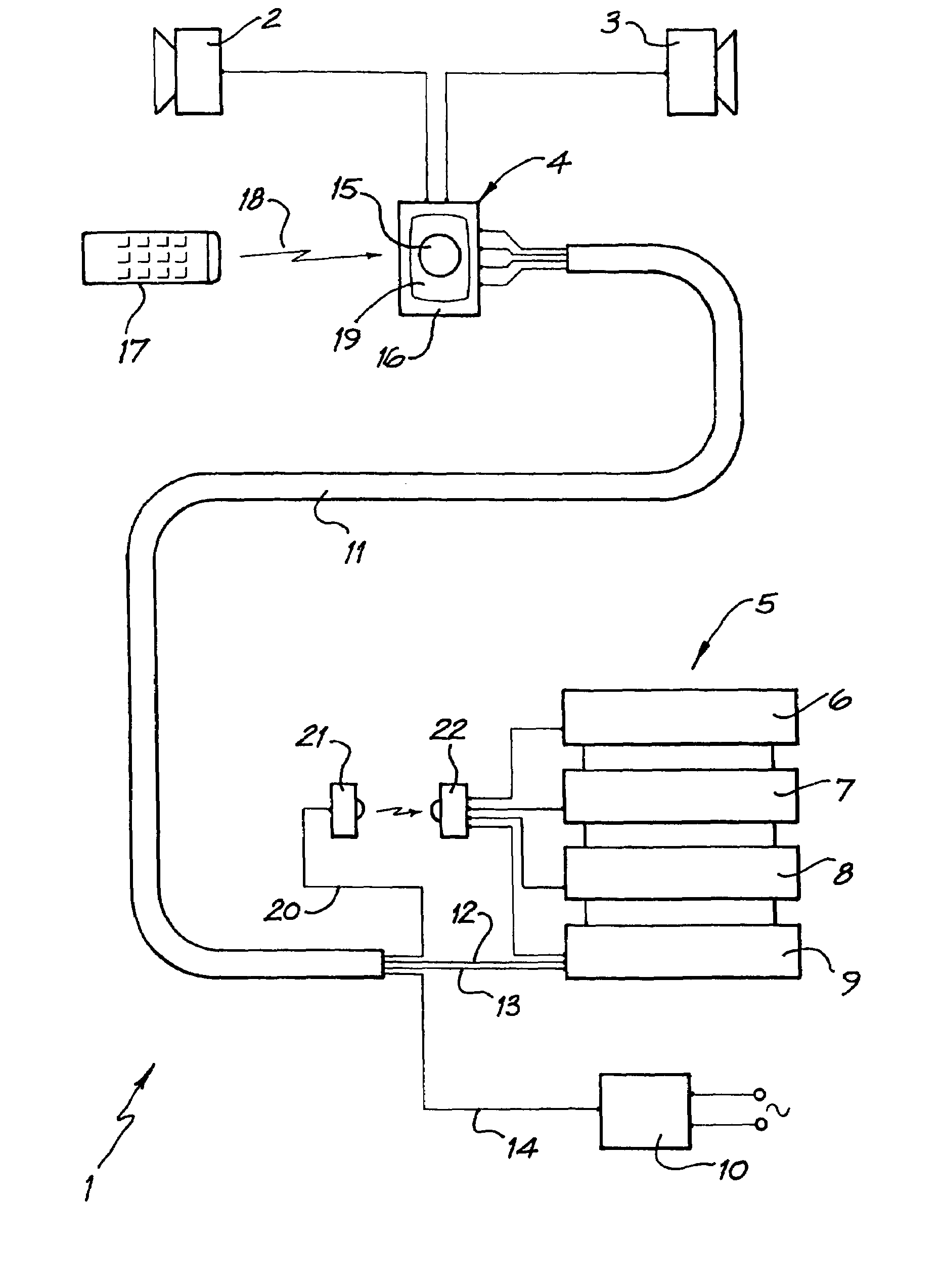
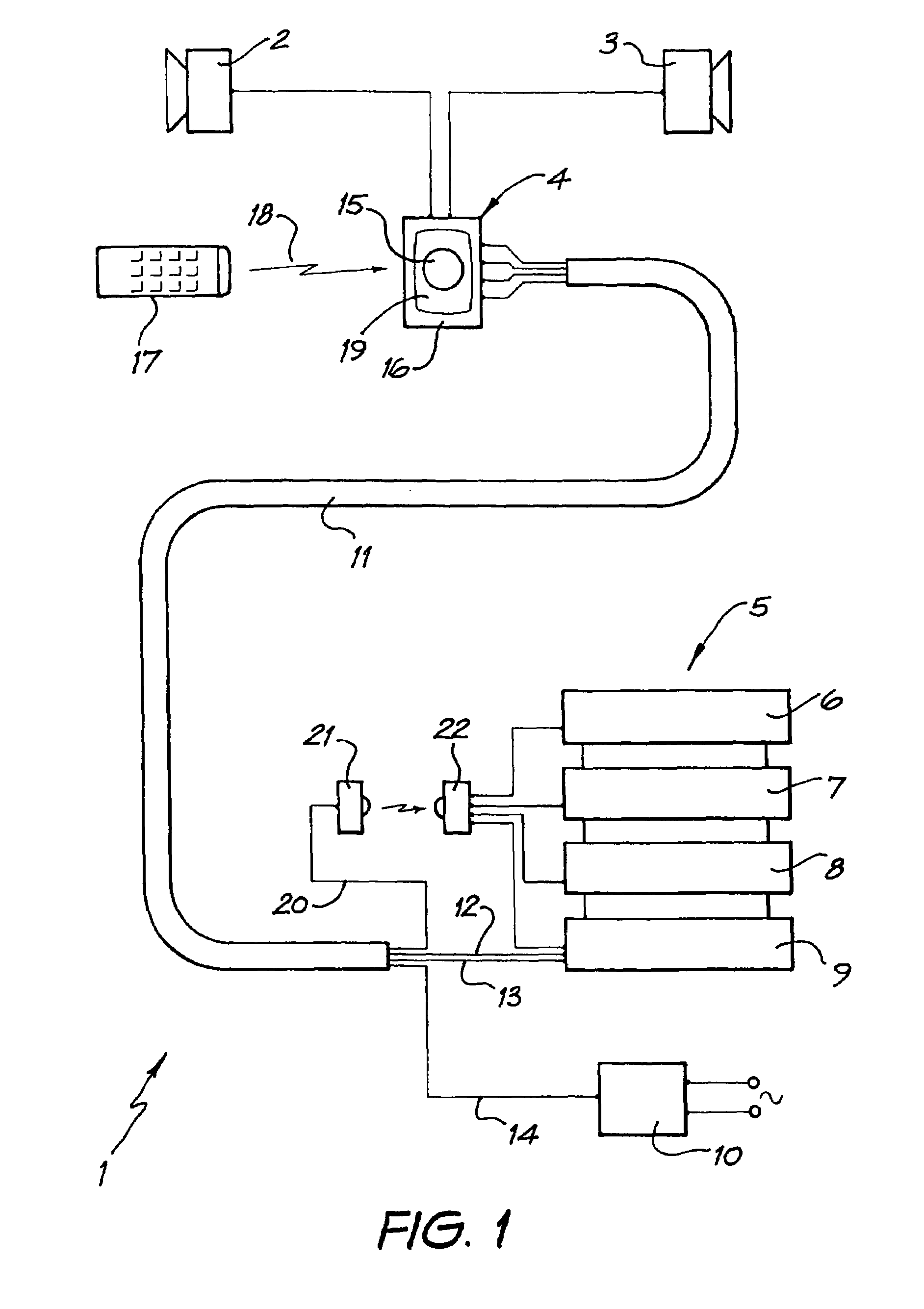
[0025]Referring first to FIG. 1, the distributed stereo audio system 1 comprises two speakers 2 and 3 connected to an amplifier 4. The amplifier 4 is housed in a standard electrical light switch housing in the same room as the speakers.

[0026]In another room, a source of audio signals 5 comprises a CD player 6, a tape recorder 7, a VCR 8 and a source selector 9. A power supply 10 provides power from the mains to each amplifier 4.

[0027]The amplifier 4 is connected to the signal source—and power supply 10 by means of a category 5 four pair twisted cable 11. One of the twisted pairs 12 provides the right audio signal from the source to amplifier 4. Another twisted pair 13 provides the left audio signal. A third twisted pair 14 provides power from power supply 10 to the amplifier 4.

[0028]In use amplifier 4 amplifies the left and right standard line level signals and supplies them to the speakers 2 and 3 respectively. The amplifier is controlled by operation of a potentiometer 15 mounted ...


PUM


Abstract

This invention concerns a distributed stereo audio system (1). Distributed stereo audio systems are used to provide stereo sound to several rooms or areas from a single source of signal. The system includes two or more speakers (2, 3) for the broadcast of stereo audio signals; a source of stereo audio signals; a stereo amplifier (4) to amplify stereo audio signals and drive the speakers; and a mains operated electrical power supply (10) to provide power to the amplifier. The amplifier is located in the same room as the speakers, and remote from the signal source and power supply. The amplifier is connected to the signal source and power supply by means of a category 5 four pair twisted cable (11) which provides, in respective twisted pairs, right channel audio signals (12) from the signal source to the amplifier, left channel audio (13) from the signal source to the amplifier, DC power (14) from the power supply to the amplifier, and control signals (20) from the amplifier to the signal source.

Description

TECHNICAL FIELD[0001]This invention concerns a distributed stereo audio system. Distributed stereo audio systems may be used to provide stereo sound to several rooms or areas from a single source of audio signals.BACKGROUND ART[0002]A typical stereo audio system comprises several audio signal sources such as a CD player and a tuner. The source units are generally arranged in a stack together with a selector and amplifier unit. In use, a signal from a selected source is amplified and provided to speakers which are typically located some distance away from the unit within the same room. The system controls are manually operable switches and dials on the signal sources and amplifier. There is sometimes a hand-held control device which is used to transmit infrared signals to the selector and amplifier unit.[0003]In sophisticated systems several sets of speakers may be mounted in different rooms throughout a house. Sometimes the selector and amplifier unit will be provided with switches ...

Claims


Application Information

Patent Timeline
Patent Type & Authority Patents(United States)
IPC IPC(8): H04B3/00H04R5/04H04R3/12H04R5/02H04R27/00H04S1/00
CPCH04R5/02H04R27/00H04R2227/005
Inventor ANDREWS, LEONARD COLINGOLDFINCH, ANDREW CHARTRES
Owner LEISURETECH ELECTRONICS
Learn More