Striker mechanism for bell unit

a bell unit and striker technology, applied in the field of bell units, can solve the problems of inconvenience in use, presenting an awkward appearance, and the orientation of the striker may be angularly displaced, and achieve the effect of inexpensive construction

Inactive Publication Date: 2007-02-27
TOKYO BELL SEISAKUSHOKK
View PDF10 Cites 13 Cited by
  • Summary
  • Abstract
  • Description
  • Claims
  • Application Information

AI Technical Summary

Benefits of technology

[0005]In view of the foregoing, the invention intends to provide a striker mechanism for a bell unit which can be constructed inexpensively and which can prevent the orientation of a striker from being changed to disable its use.
[0007]According to the present invention, the striker, which is maintained by the leaf spring member at an intermediate position as viewed in the rocking direction, can be rocked in a direction away from the bell against the resilience of the leaf spring member. If the finger is now released, the striker is rocked toward the bell under the resilience of the leaf spring member to impact it, thus clanging the bell.
[0008]Since the striker mechanism can be constructed with the support member, the leaf spring member and the striker, it can be manufactured inexpensively as in the prior art.
[0009]Since the striker is pivotably mounted on the support member so as to be rockable, the occurrence of a change in the orientation of the striker to disable its use as experienced when the coiled spring is used as in the prior art is prevented, allowing it to be used in a stable manner over a prolonged period of time.

Problems solved by technology

The striker mechanism arranged as mentioned above offers an advantage that it can be manufactured inexpensively because it can be constructed with the support member, the coiled spring and the striker, but the use of the coiled spring causes a disadvantage that the orientation of the striker may be angularly displaced as much as 45°, for example, if an excessive magnitude of force is applied thereto, presenting an inconvenience in use or presenting an awkward appearance.
In addition, if the coiled spring is stressed more than is required, it may be worn out to be of no use.

Method used


Image

  • Striker mechanism for bell unit
  • Striker mechanism for bell unit
  • Striker mechanism for bell unit

Examples


Embodiment Construction

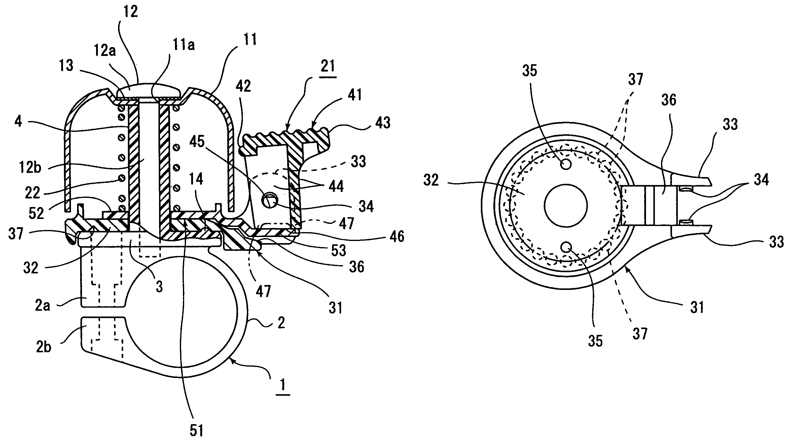
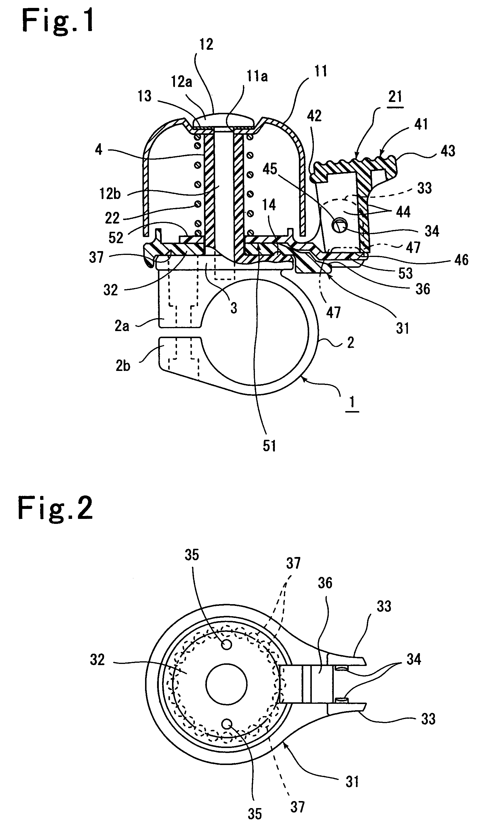
[0015]An embodiment of the invention shown in the drawings will now be described. In FIG. 1, a bell unit is adapted to be mounted by a bell mounting member 1 on a handle of a bicycle or a tricycle, not shown.

[0016]The bell mounting member 1 is formed of a synthetic resin material and includes a grip 2 which is disposed in surrounding relationship with a handle and connected thereto, a disc 3 disposed on top of the grip 2, and a hollow support shaft 4 extending from a central portion of the disc 3 in a direction which is approximately radially outward of the handle, all in an integral manner. The grip 2 and the support shaft 4 may be separate from each other and connected together.

[0017]The grip 2 of the bell mounting member 1 is disposed in surrounding relationship with the handle, but is cut at a portion to leave the opposite ends in abutment against each other. While not shown, a nut embedded in one end 2a is threadably engaged by a bolt which is passed through the other end 2b, a...


PUM


Abstract

A striker mechanism 21 which clangs a bell 21 is made up of a support member 31 which projects radially outward of the bell, a striker 41 pivotably mounted on the support member so as to be rockable in a direction toward and away from the outer peripheral surface of the bell, and a leaf spring member 41 for maintaining the striker at an intermediate position as viewed in the rocking direction which is by a given distance spaced from the bell. The striker is formed at its one end with an impactor 42 which impacts the bell and an operator 43 which operates the striker for rocking motion and is formed at the other end with a spring abutment 46 against which the leaf spring member resiliently abuts, an intermediate portion between the opposite ends being pivotably mounted on the support member so as to be rockable. The striker 41 is pivotably mounted on projections 33 so as to be rockable, and accordingly, if an excessive magnitude of force is applied to the striker 41, a displacement of its orientation can be prevented.

Description

FIELD OF THE INVENTION[0001]The present invention relates to a bell unit which is preferred for use on a bicycle or tricycle, and more particularly, to an improvement in a striker mechanism for a bell unit.DESCRIPTION OF THE PRIOR ART[0002]A bell unit is well known in the art which comprises a bell mounting member which is mounted on a handle of a bicycle, a bell mounted on the bell mounting member and a striker mechanism mounted on the bell mounting member for clanging the bell.[0003]The present applicant has previously proposed a striker mechanism which comprises a support member projecting radially outward from the bell and a striker mounted on the support member through a coiled spring so as to be rockable toward and away from the outer peripheral surface of the bell (Registered Utility Model No. 2,520,590).[0004]The striker mechanism arranged as mentioned above offers an advantage that it can be manufactured inexpensively because it can be constructed with the support member, t...

Claims


Application Information

Patent Timeline
Patent Type & Authority Patents(United States)
IPC IPC(8): G10K1/072
CPCG10K1/072B62J3/04
Inventor ICHIMURA, KYOJIISHIWA, MOTOHISASEKI, KAZUHARU
Owner TOKYO BELL SEISAKUSHOKK
Why Eureka
Try Eureka