Dual position hearing protection device

a hearing protection device and dual position technology, applied in the field of hearing protection devices, can solve the problems of increasing the user's desire to remove the ear plug frequently, difficulty in conversation, and pressure difference between the atmosphere and the inner ear, so as to reduce sound attenuation, facilitate switching, and more normal hearing and conversation

Active Publication Date: 2007-02-27
MARSH ROBERT E
View PDF6 Cites 25 Cited by
  • Summary
  • Abstract
  • Description
  • Claims
  • Application Information

AI Technical Summary

Benefits of technology

[0010]It is an object of this invention to provide a hearing protection device that can be easily switched from a position of substantial hearing protection and sound attenuation to a position of reduced sound attenuation which permits more normal hearing and conversation. A further object of this invention to provide a hearing protection device that the user does not need to remove in order to carry on normal conversation. Still another object of the invention is to provide a compressible ear plug that conforms to the ear canal of the user but also permits convenient switching from a position providing substantial hearing protection and sound obstruction to a position of minimal sound obstruction. Still another object of the present invention is to permit switching between minimal and maximum sound attenuation positions while keeping the ear plug fully inserted in the ear canal.

Problems solved by technology

With prior art foam earplugs, however, conversation may be very difficult because of the high level of sound attenuation afforded by the ear plug.
In addition, pressure differentials between the atmosphere and the inner ear resulting from the tight seal between the ear plug and the ear canal may be uncomfortable and may increase the user's desire to frequently remove the ear plug.
Any situation in which a user's hands may become dirty (such as in handling a firearm or in an industrial workplace setting) the recompression of the earplug for reinsertion into the ear can result in contamination of the surface of the earplug and transfer of that contamination to the ear canal of the user.
Some hearing protection devices have attempted to selectively block certain sounds, such as the ear plug disclosed in U.S. Pat. No. 6,425,398, but with limited success.
No prior art hearing protection ear plug permits a user to physically switch the ear plug between a position in which substantial hearing protection is provided, to a position in which sound is only minimally obstructed and more normal conversation can take place.

Method used


Image

  • Dual position hearing protection device
  • Dual position hearing protection device

Examples


Embodiment Construction

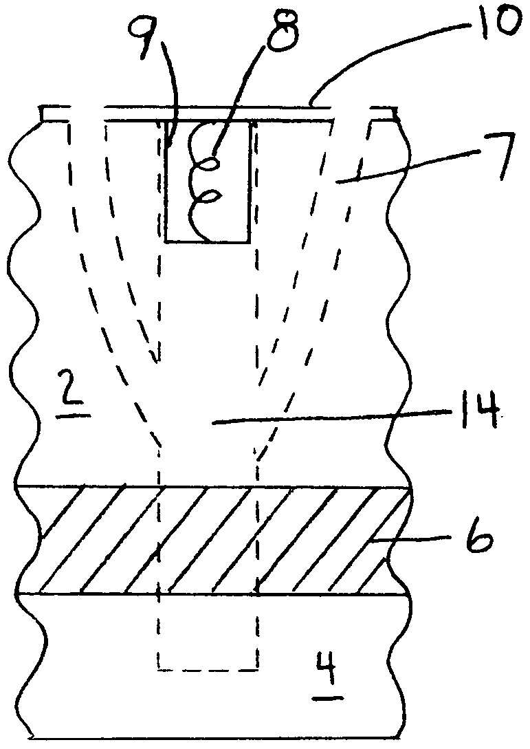
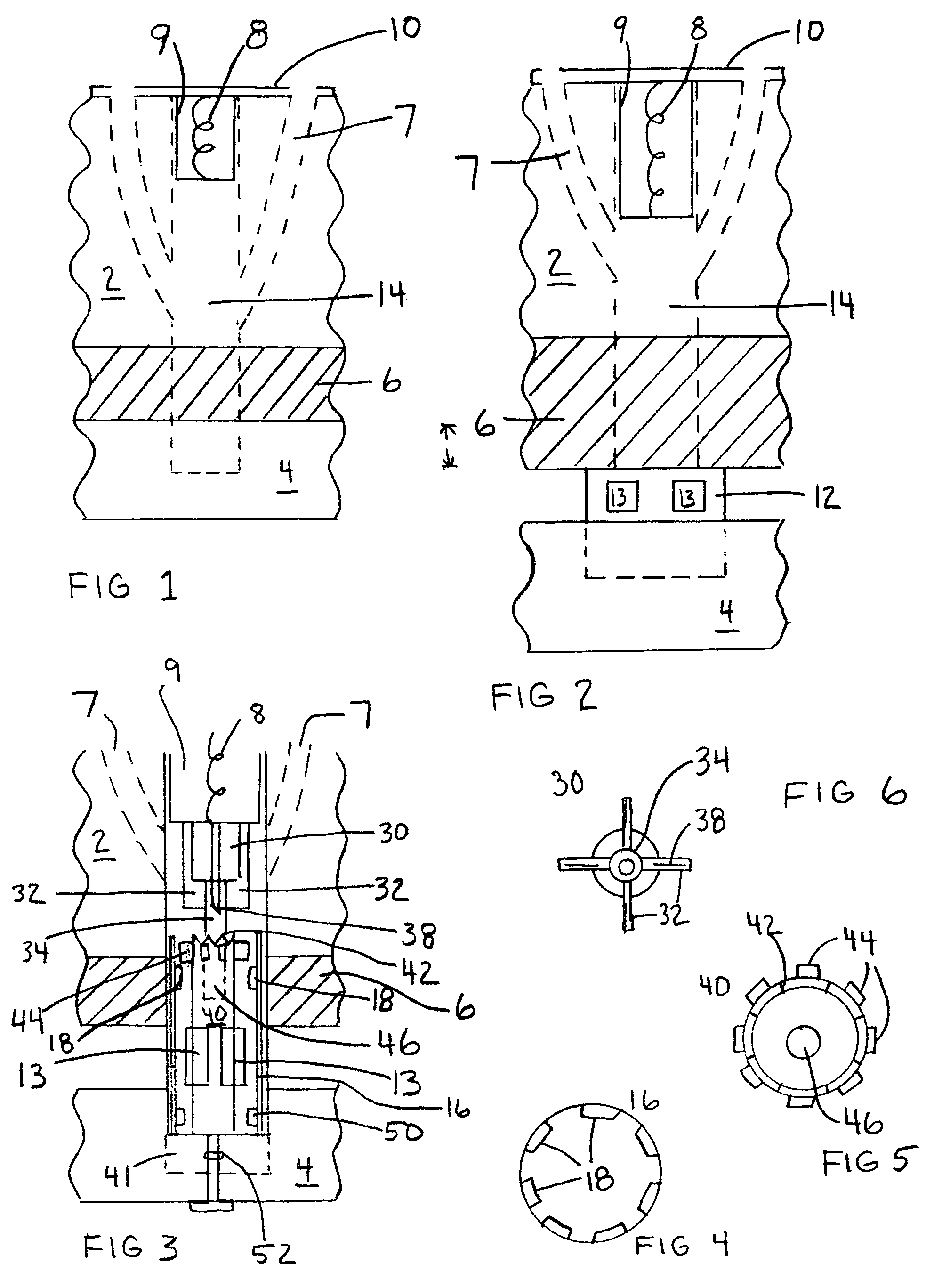
[0015]Referring to FIG. 1, a preferred embodiment of the hearing protection device is shown in the “closed” or substantial hearing protection and sound attenuation position. The ear plug includes a base plug 2 and a second plug 4. The base plug 2 includes at least a portion 6 that is resilient foam or a similar material. Ideally, the outer portions of ear plug components 2, 4, and 6, are all made of a resilient foam. The foam should be easily compressible by hand and should return to its original dimensions (or exert pressure against the ear canal of the user) when released. Suitable foams are well-known in the art. The internal structure of the earplug, described in more detail below, is located in the innerspace of base plug 2 as shown as 14 in FIG. 1. Alternatively, the internal structure could be located primarily within second plug 4. Ideally the diameter of the innerspace, 14 (and the internal components within that space as described below) are small relative to the overall d...


PUM


Abstract

The present invention is a dual position hearing protection device. In one position, the device provides substantial sound attenuation and hearing protection. In the second position, an opening in the device permits sounds to enter the ear of the user relatively unobstructed. In the preferred embodiment of this invention the position of the device is changed simply by compressing the exposed end of the earplug.

Description

CROSS-REFERENCE TO RELATED APPLICATIONS[0001]This application claims the benefit of U.S. Provisional Patent Application No. 60 / 334,713, filed Oct. 26, 2001.STATEMENT REGARDING FEDERALLY SPONSORED RESEARCH OR DEVELOPMENT[0002]Not Applicable.BACKGROUND OF THE INVENTION[0003]1. Field of the Invention[0004]The present invention generally relates to devices for the protection of human hearing, and more particularly, to a hearing protection device that can be easily changed between a position which provides substantial hearing protection and a second position that permits more normal sound transmission.[0005]2. Description of the Prior Art[0006]Resilient foam ear plugs are widely used to provide hearing protection. These foam ear plugs are sometimes referred to as “self-adjustable.” The generally tubular foam earplug is compressed and inserted into the ear canal, where it expands and conforms to the ear canal. In its expanded position, this foam earplug provides a high level of hearing pr...

Claims


Application Information

Patent Timeline
Patent Type & Authority Patents(United States)
IPC IPC(8): A61F11/06
CPCA61F11/08
Inventor MARSH, ROBERT E.
Owner MARSH ROBERT E
Why Eureka
Try Eureka