Coaxial cable connector

a technology of coaxial cable and connector, which is applied in the direction of coupling device connection, electrical discharge lamp, coupling device details, etc., can solve the problems of increased contact resistance, reduced signal strength, and excessive rf leakage of the connector, so as to achieve the effect of simple and inexpensive connector, fast installation, and easy machined

Active Publication Date: 2007-02-27
PPC BROADBAND INC
View PDF33 Cites 92 Cited by
  • Summary
  • Abstract
  • Description
  • Claims
  • Application Information

AI Technical Summary

Benefits of technology

[0035]Accordingly, a simple and inexpensive connector is disclosed herein that can easily be machined from a small number of components, and which can be quickly installed over the prepared end of a coaxial cable, for example by using a conventional axial compression installation tool. The connector preferably forms a reliable moisture proof seal between the connector and the jacket of the coaxial cable to preclude moisture from passing between the connector and the jacket of the coaxial cable extending therein. Preferably, the connector disclosed herein avoids the need for gels or other sealing compounds, although gels or other sealing compounds could be provided for additional strength and / or sealing. Furthermore, the connector disclosed herein provides a connector or connector / coaxial cable assembly or method which results in a pull-out strength which reduces dislodgement of the cable from the connector following installation.

Problems solved by technology

It is known in the art that the passage of moisture between the coaxial cable jacket and the surrounding F-connector can lead to corrosion, increased contact resistance, reduced signal strength, and excessive RF leakage from the connector.
However, the connector shown in the Hayward '274 patent is much more expensive than conventional F-connectors and can not be installed quickly, as by a simple crimp or compression tool; rather, the mating threads of such connector must be tightened, as by using a pair of wrenches.

Method used


Image

  • Coaxial cable connector
  • Coaxial cable connector
  • Coaxial cable connector

Examples


Embodiment Construction

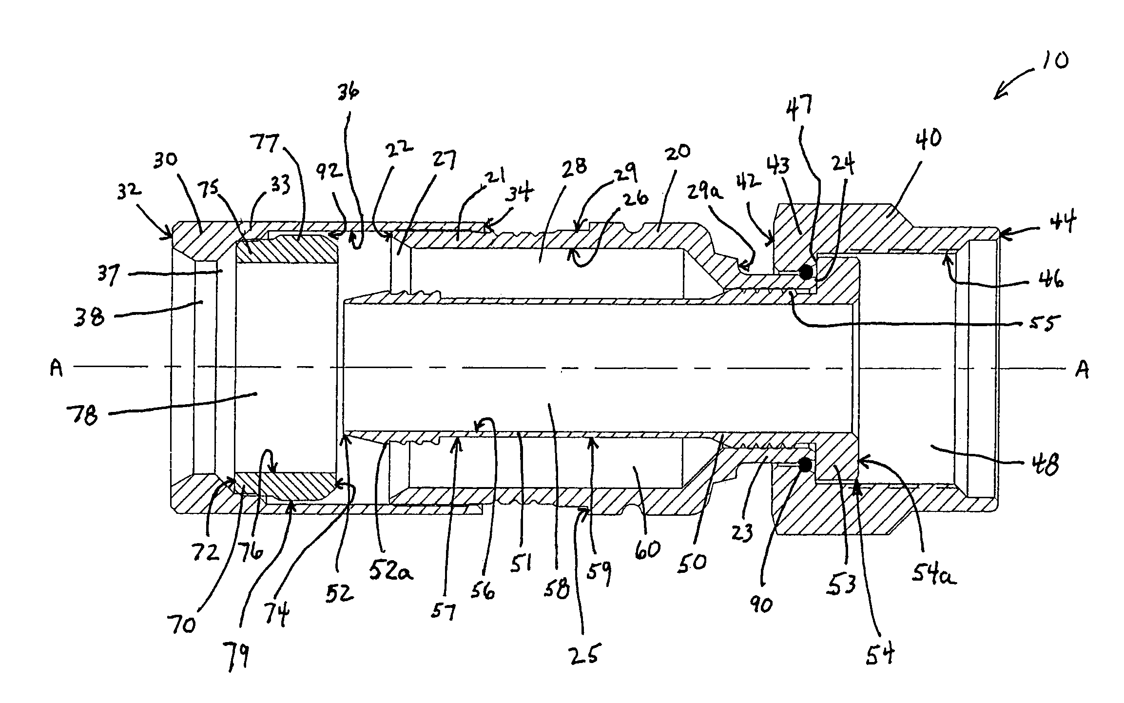
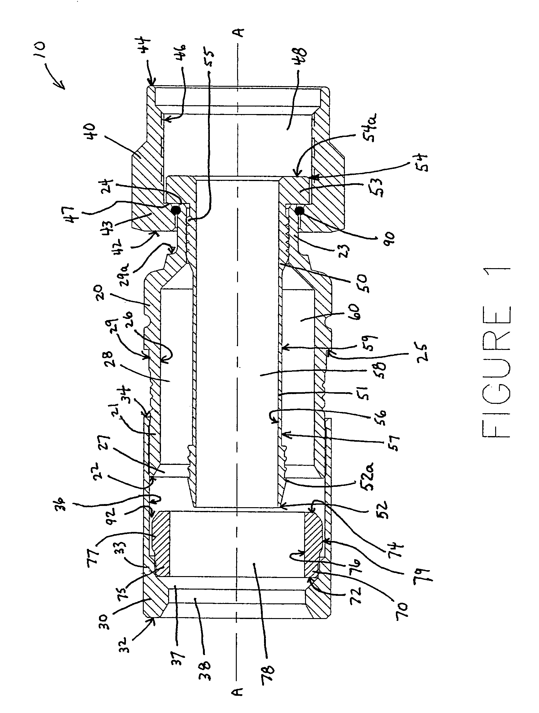
[0050]Reference will now be made in detail to the present preferred embodiment(s) of the invention, examples of which are illustrated in the accompanying drawings. Whenever possible, the same reference numerals will be used throughout the drawings to refer to the same or like parts. One embodiment of the present invention is shown in FIG. 1, and is designated generally throughout by the reference numeral 10.

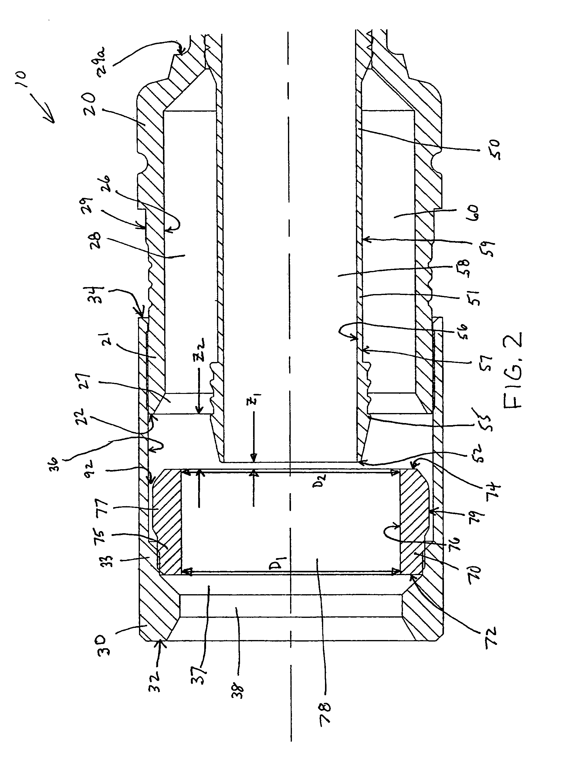
[0051]FIG. 1 schematically illustrates one preferred embodiment of a connector, as disclosed herein, comprising a compression ring in a rearward position. FIG. 2 is an enlarged view of FIG. 1. FIG. 3 schematically illustrates a coaxial cable inserted into the connector of FIG. 1, or, alternatively, the connector inserted onto the cable. FIG. 4 schematically illustrates the connector of FIG. 1 in conjunction with two portions of a tool used to compress the connector together such that the compression ring moves into a forward position, wherein the connector is shown in FIG. 4 in a...


PUM


Abstract

A connector for coaxial cable is disclosed herein which has a gripping ring positioned between a compression ring and a connector body. At least two opposed ends of the gripping ring are capable of being displaced radially inwardly for gripping the cable.

Description

[0001]This application is a continuation-in-part application of application Ser. No. 11 / 012,507, filed on Dec. 14, 2004, now U.S. Pat. No. 7,018,235.BACKGROUND OF THE INVENTION[0002]1. Field of the Invention[0003]The present invention relates generally to coaxial cable connectors, and particularly to coaxial cable connectors capable of being connected to a terminal.[0004]2. Technical Background[0005]Coaxial cable connectors such as F-connectors are used to attach coaxial cable to another object such as an appliance or junction having a terminal adapted to engage the connector. Coaxial cable F-connectors are often used to terminate a drop cable in a cable television system. The coaxial cable typically includes a center conductor surrounded by a dielectric, in turn surrounded by a conductive grounding foil and / or braid (hereinafter referred to as a conductive grounding sheath); the conductive grounding sheath is itself surrounded by a protective outer jacket. The F-connector is secure...

Claims


Application Information

Patent Timeline
Patent Type & Authority Patents(United States)
IPC IPC(8): H01R9/05
CPCH01R9/0518H01R9/0521H01R9/0527H01R9/0524H01R13/622H01R9/05
Inventor BURRIS, DONALD A.
Owner PPC BROADBAND INC
Why Eureka
Try Eureka