
Dipole antenna

a dipole antenna and antenna technology, applied in the field of dipole antennas, can solve the problems of limited radiation distance and need for adding power supply, and achieve the effect of low profile construction and easy manufacturing

Inactive Publication Date: 2007-02-27
HON HAI PRECISION IND CO LTD
View PDF9 Cites 10 Cited by
  • Summary
  • Abstract
  • Description
  • Claims
  • Application Information

AI Technical Summary

Benefits of technology

[0006]It is an object of the present invention to provide a dual band dipole antenna, which has a low profile construction and can be manufactured easily.
[0007]To achieve the aforementioned object, the present invention provides a dual-band antenna which has two dipoles. The first dipole antenna comprises a first radiating element disposed at a first plane and a first ground portion disposed at a second plane. The second dipole antenna comprises a second radiating element disposed at the first plane and a second ground portion disposed at the second plane. The first and the second radiating elements are formed of a first member and the first and second ground portions are formed of a conjugated member. The first member has the same shape and dimension as that of the conjugated member. Therefore, when the first member is fabricated, the conjugated member is fabricated as well, and thus manufacture time and costs will be reduced. The first and second radiating elements both further consist a compensating portion for improving radiating patterns and a broadband portion for improving resonating bandwidth of the first and second dipole antennas. A feed line has its inner conductor connect to radiating elements and outer conductor connect to ground portions.

Problems solved by technology

However, the radiation distance is limited by power supplied to the antenna, so if we want to realize far-distance communication in all direction, adding power supply is needed.

Method used


Image

  • Dipole antenna
  • Dipole antenna
  • Dipole antenna

Examples


Embodiment Construction

[0018]Reference will now be made in detail to a preferred embodiment of the present invention.

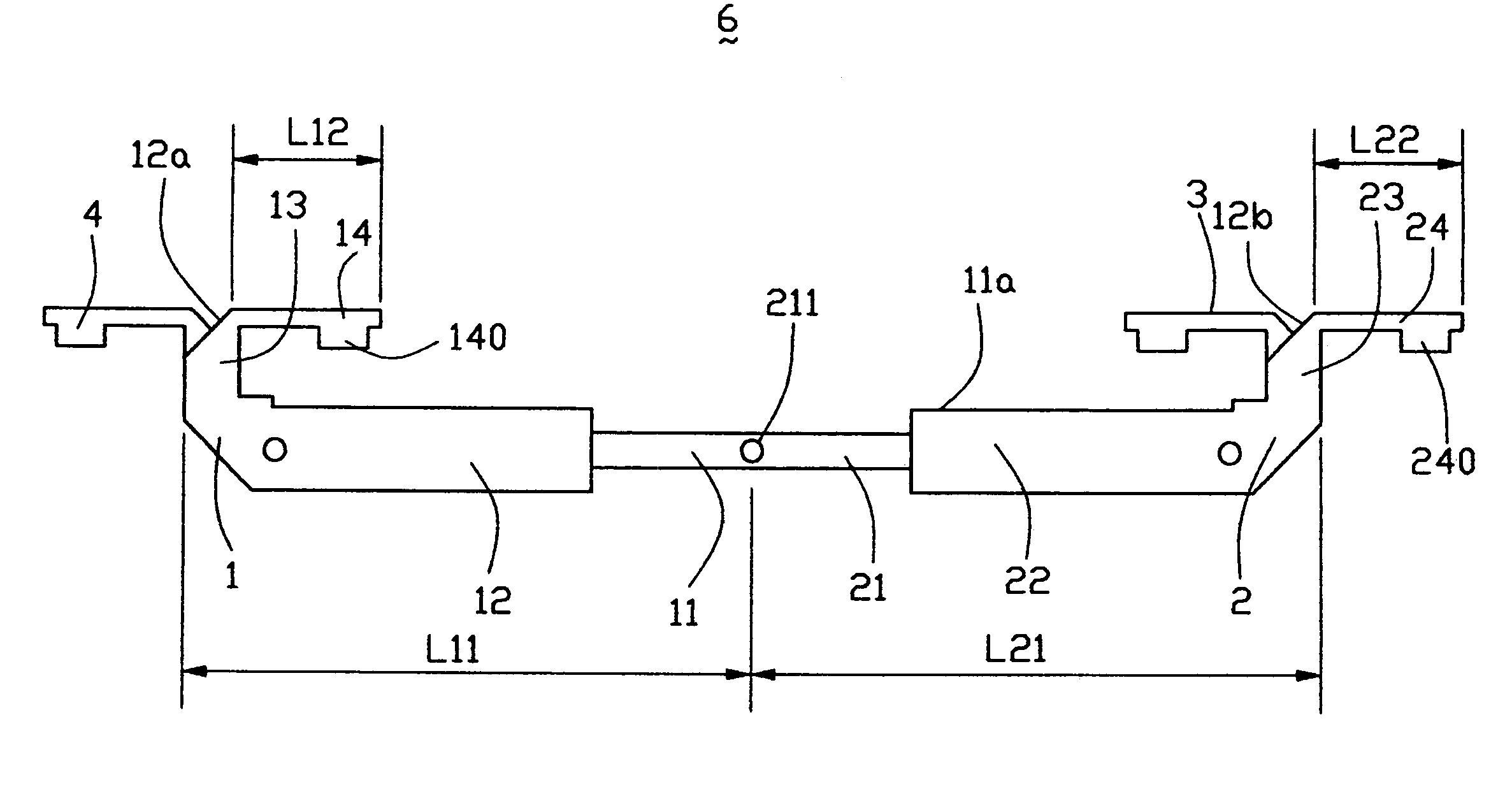
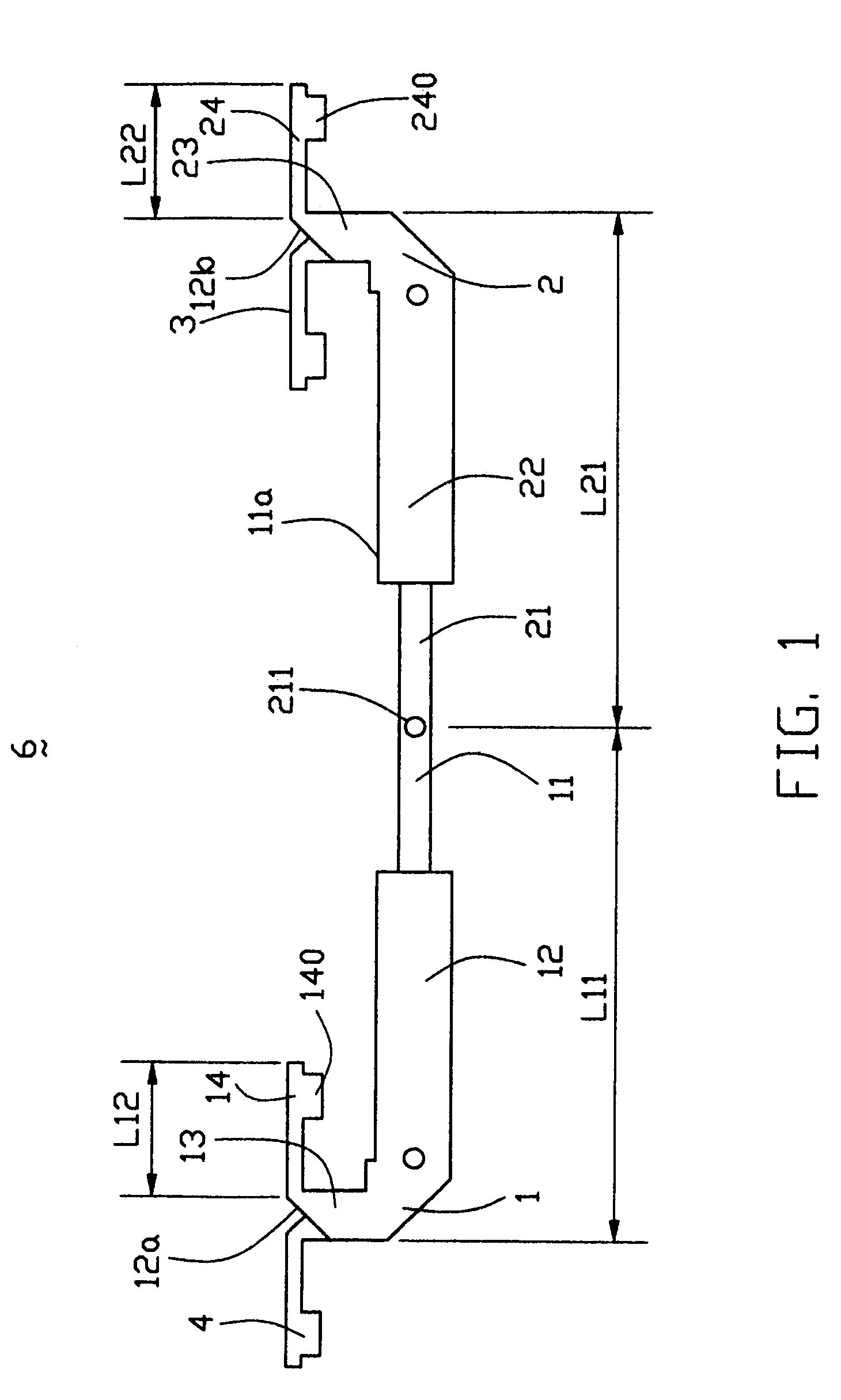
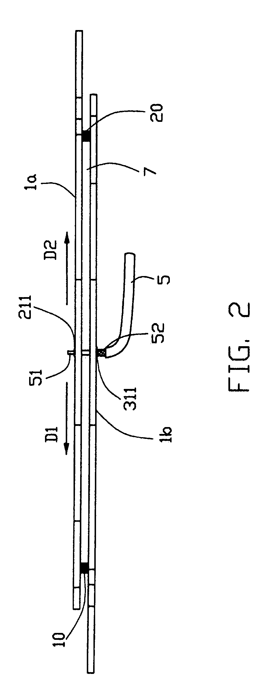
[0019]Referring to FIG. 1 and FIG. 2, a dual-band antenna 6 in accordance with a preferred embodiment of the present invention is constituted by forming a first and second dipole antenna each having a radiating element 1, 2 and a ground portion 3, 4 and a feed line 5 coupled to the dipole antennas through welding holes 211, 311. In order to assemble the above-described antenna, the radiating elements 1, 2 are formed integrally as a first member 1a, while the ground portions 3, 4 are formed integrally as a conjugated member 1b with respect to the first member 1a. The first member 1a and conjugated member 1b are parallel to each other and arranged in two different planes.

[0020]The first member 1a and the conjugated member 1b are identical in construction and thus only the first member 1a will be described in detail. The first member 1a comprises a first base member 11a, and a pair of radiatin...


PUM


Abstract

A dual-band antenna for communication device includes a first dipole antenna, a second dipole antenna and a coaxial feed line. The first dipole antenna includes a first radiating element disposed at a first plane and a first ground portion disposed at a second plane. The second dipole antenna includes a second radiating element disposed at a first plane and a second ground portion disposed at a second plane. The feed line includes an inner conductor electrically connecting to the first and second radiating elements and an outer conductor electrically connecting to the first and second ground portions. The first and second radiating elements both further include a compensating portion for improving radiating patterns of the first and second dipole antennas and a broadband portion for increasing frequency bands of the first and second dipole antennas.

Description

BACKGROUND OF THE INVENTION[0001]1. Field of the Invention[0002]The present invention relates generally to an antenna, and more particularly to a dipole antenna for a wireless communication device.[0003]2. Description of the Prior Art[0004]A dipole antenna is a straight electrical conductor measuring ½ wavelength from end to end and connected at the center to a radio frequency (RF) feed line. This antenna, also called a doublet, is one of the simplest types of antenna, and constitutes the main RF radiating and receiving element in various sophisticated types of antenna. The dipole is inherently a balanced antenna, because it is bilaterally symmetrical. According to that, the dipole antenna exhibits a symmetric radiation pattern. A symmetric radiation pattern provides uniform gain in 360 degrees, thereby allowing equally effective communication in all directions. However, the radiation distance is limited by power supplied to the antenna, so if we want to realize far-distance communi...

Claims


Application Information

Patent Timeline
Patent Type & Authority Patents(United States)
IPC IPC(8): H01Q9/28H01Q19/10H01Q21/30
CPCH01Q9/28H01Q21/30H01Q19/10
Inventor DAI, HSIN-KUOKE, YUN-LONGTAI, LUNG-SHENGYANG, SHU-CHENKUO, CHIN-PAO
Owner HON HAI PRECISION IND CO LTD
Learn More