
Load cell with roberval mechanism

a roberval mechanism and load cell technology, applied in the direction of instruments, apparatus for force/torque/work measurement, traction measurement, etc., can solve the problems of inability to act, increase measurement time, and defective roberval mechanism, so as to maintain linearity and span performance, reduce manufacturing cost, and reduce the effect of profile construction

Inactive Publication Date: 2008-02-26
TANITA CORP
View PDF3 Cites 3 Cited by
  • Summary
  • Abstract
  • Description
  • Claims
  • Application Information

AI Technical Summary

Benefits of technology

The present invention provides a load cell with a unique design that allows for accurate measurements of force and pressure. The load cell includes a Roberval mechanism with two parallel arms and four strain-generating-portions. The strain-generating-portions are evenly distributed on each arm and are made of the same thickness. The load cell can be fixed with a strain gauge adhesion surface on the first arm and a load can be applied vertically over the first arm. The second arm can be formed in a way that its neutral axis is displaced from the load cell's neutral axis by a predetermined distance, or only the second arm can be reduced in thickness. This design allows for accurate and reliable load cell readings.

Problems solved by technology

However, such Roberval mechanism is defective in that it has no possibility of acting as the ideal mechanism because of the fact that the links have integral construction to mutually provide adverse effect.
Furthermore, because of longer period of time taken before load becomes stable the increased measurement time may be necessary.
In addition, to keep the thickness of the arms, the strain-generating-body having larger size becomes necessary, which does not lend itself to provide lower profile construction and miniaturization.

Method used


Image

  • Load cell with roberval mechanism
  • Load cell with roberval mechanism
  • Load cell with roberval mechanism

Examples


embodiment 1

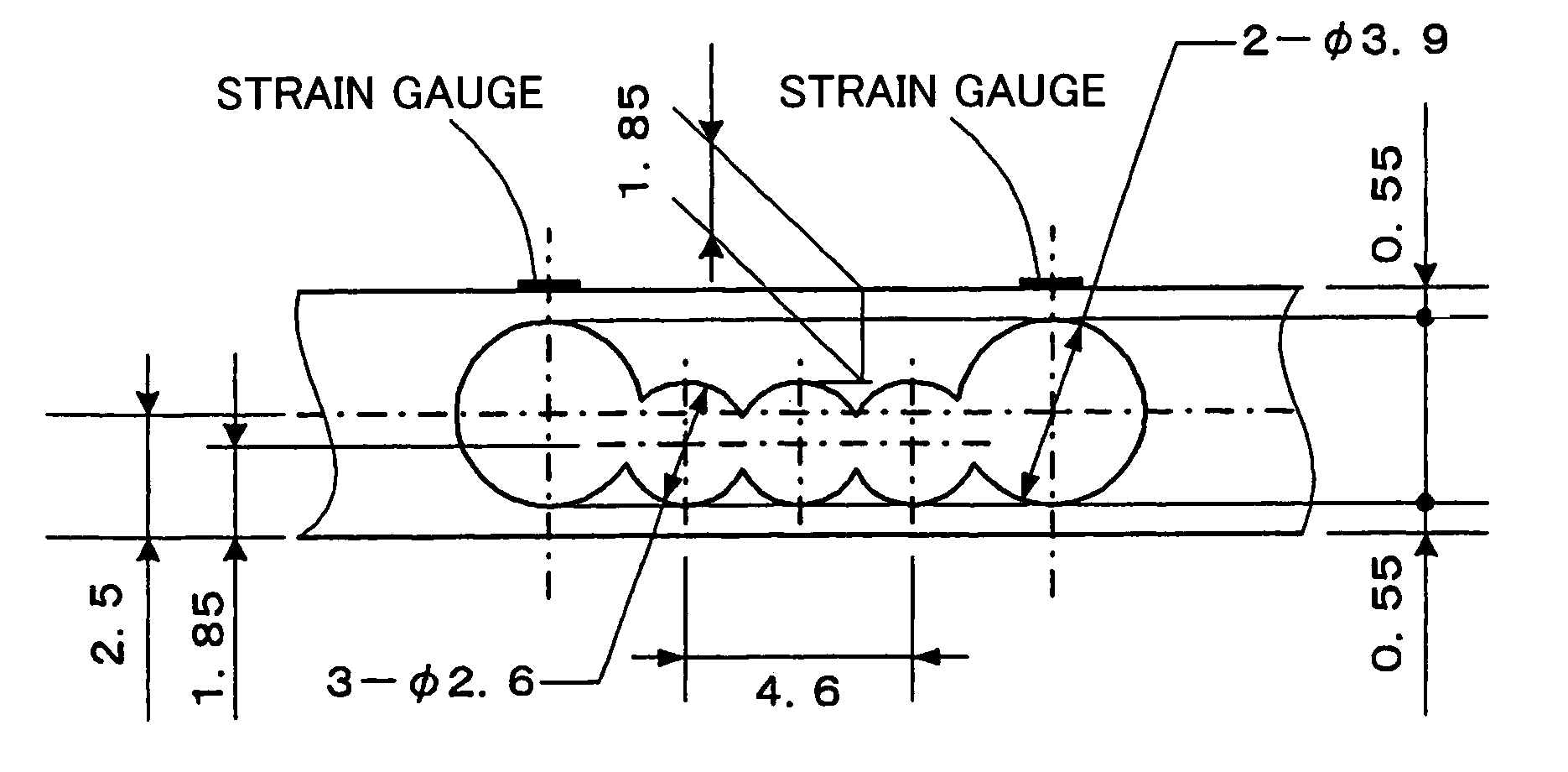
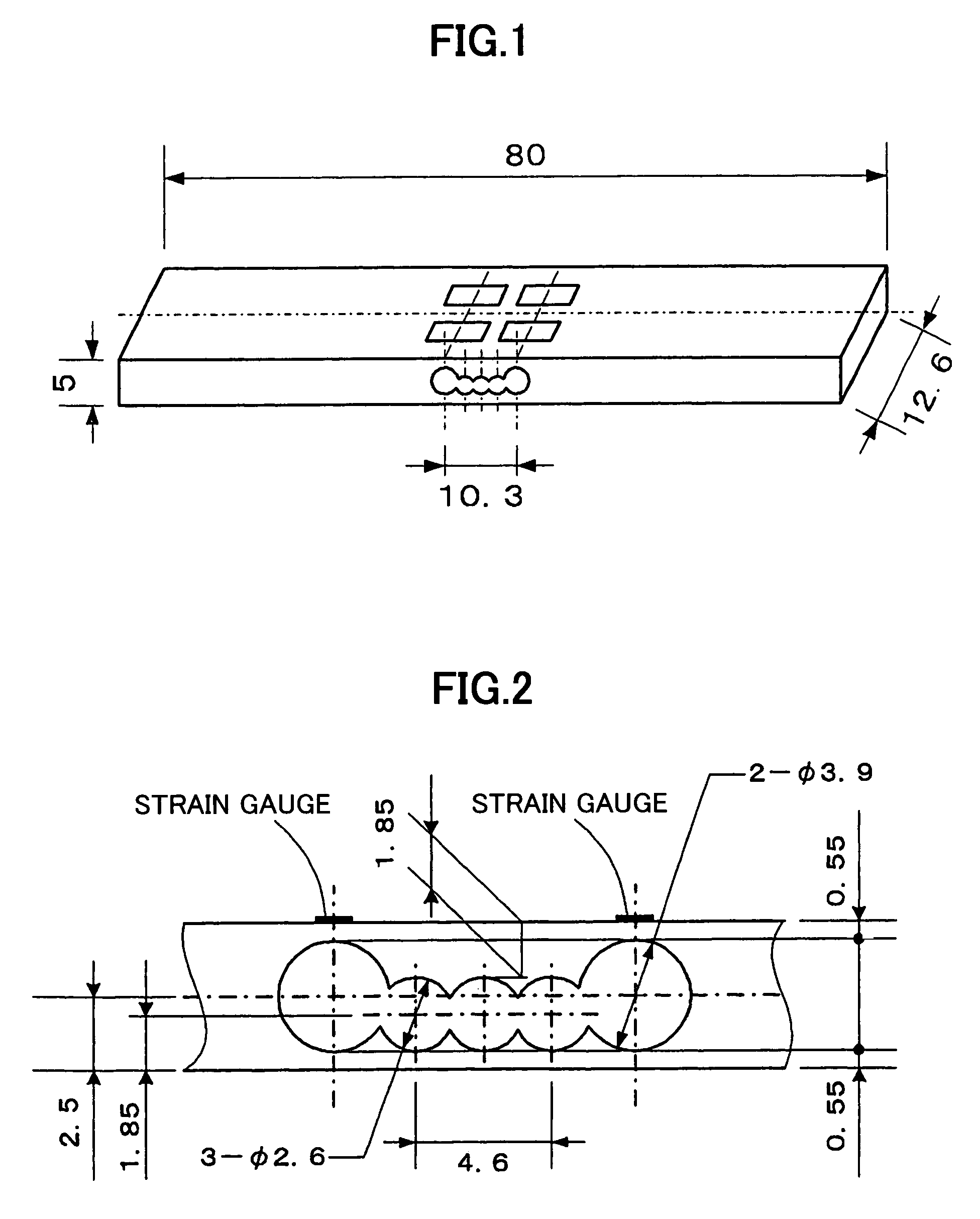
[0050]The present inventors have paid their attention to the fact that, in a load cell of Roberval type with strain gauges adhered to strain-generating-portions in one of two arms, any flexure of the entire strain-generating-body in the cantilevered form affects the upper and lower arms and the strain-generating-portions to degrade the linearity performance. Then, they have experimentally found that by making the strain-generating-portions to have same thickness, but making the upper and lower arms to have different thickness, the arm having greater thickness creates the linearity of strain in the strain-generating-portions thereof.

[0051]More concretely, it is preferable to provide proper difference in thickness between the upper and lower arms in such manner that, by making the lower arm thinner than the upper arm, the compressive and tensile force exerted in the upper and lower arms due to flexure of the entire strain-generating-body is supported mainly by the lower arm to balance...

embodiment 2

[0072]The present invention additionally provides Embodiment 2 in which a highly precise load cell is realized simply by adjusting the thickness of a second arm. In Embodiment 1, as described above, on the basis of a load cell in which a channel for forming strain-generating-portions and arms is formed from a plurality of round apertures in a strain-generating-body, an axis of the channel is displaced while keeping the width of the channel to provide different thickness for the upper and lower arms. In contrast thereto, Embodiment 2 of the present invention provide another load cell in which a second arm is only made thinner to widen a channel so that different thickness is provided for first and second arms. Embodiment 2 is useful especially for a relatively large load cell in which both arm have sufficient thickness.

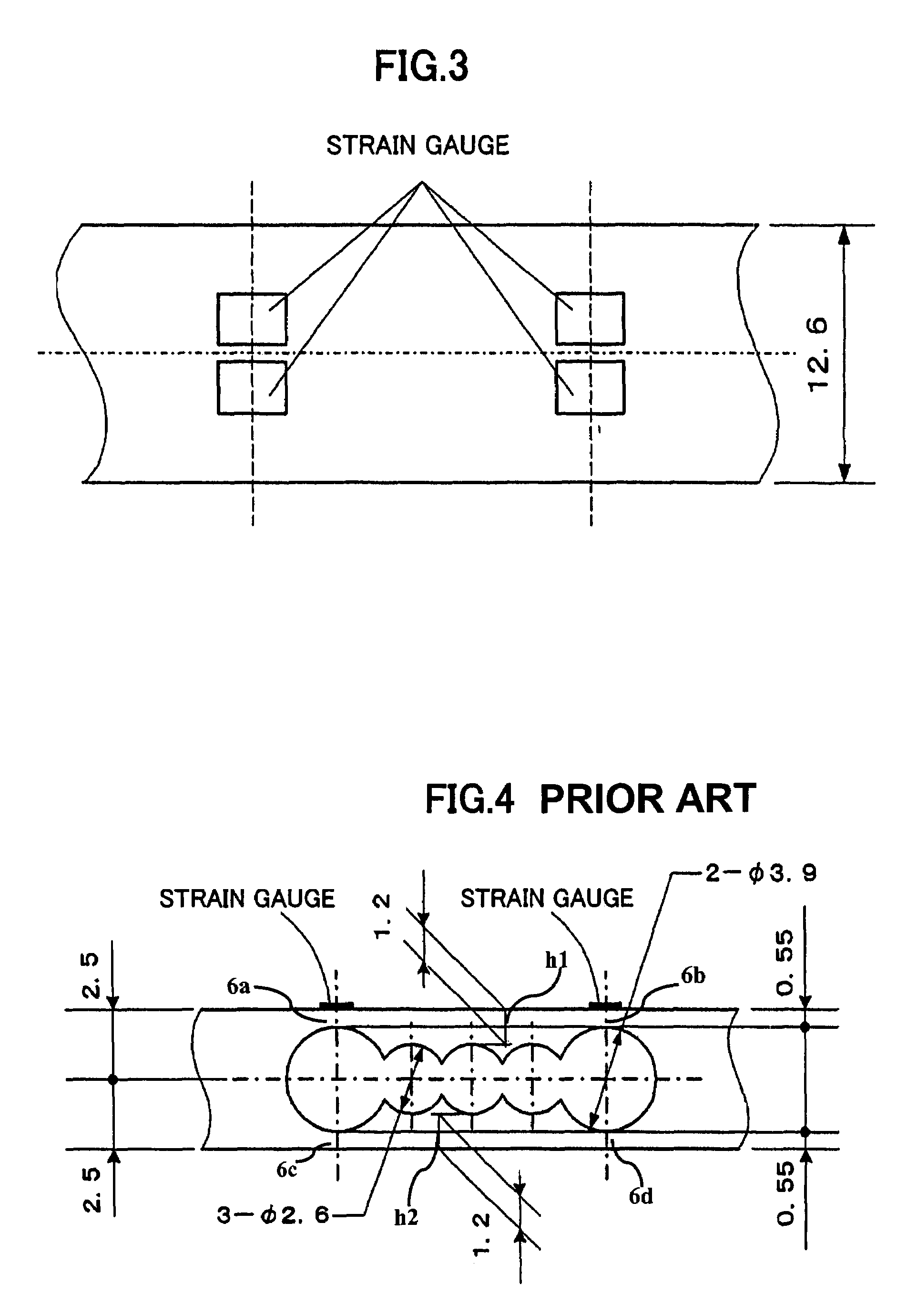
[0073]FIG. 15 illustrates a load cell of the prior art in which arms h1 and h2 have same thickness, and strain-generating-portions 6a, 6b, 6c and 6d have same thicknes...


PUM

PropertyMeasurementUnit
widthaaaaaaaaaa
widthaaaaaaaaaa
thicknessaaaaaaaaaa

Abstract

Disclosed is a load cell including a Roberval mechanism having two parallel arms between a fixed end and a movable end, and four strain-generating portions, arranged such that two of the strain-generating portions are coupled to each other on each of the two arms. In certain embodiments, the four strain-generating-portions all have the same thickness, and the two arms include a first arm having strain gauges adhered to each of two of the strain-generating portions coupled to each other, and a second arm having a thickness smaller than that of the first arm.

Description

BACKGROUND OF THE INVENTION[0001]1. Field of the Invention[0002]The present invention relates to a load cell comprising a Roberval mechanism made up of two parallel arms and of four strain-generating-portions provided in such way that two strain-generating-portions are coupled to each other on each of the two arms.[0003]2. Prior Art[0004]A typical load cell 1 comprising a Roberval mechanism that has been used in the prior art is illustrated in FIG. 19. The load cell 1 includes a strain-generating-body 2 and strain gauges 3a, 3b, 3c and 3d. In particular, the strain-generating-body 2 includes a fixed end 4 and a movable end 5 to act as a cantilever. The strain-generating-body 2 further includes, between the fixed end 4 and the movable end 5, an aperture 7 for strain-generating-portions 6a and 6c and an aperture 8 for strain-generating-portions 6b and 6d each for detection of strain by the strain gauges adhered thereon. A channel 9 communicating between the apertures 7 and 8 is provid...

Claims


Application Information

Patent Timeline
Patent Type & Authority Patents(United States)
IPC IPC(8): G01L1/22
CPCG01G3/1412G01L1/2243
Inventor TSUTAYA, TAKAOYABE, YUZO
Owner TANITA CORP
Learn More