
High efficiency and high power patch antenna and method of using

a patch antenna and high-efficiency technology, applied in the field of high-power patch antennas, can solve the problems of dissipation of 30 w within the antenna structure, achieve the effect of maintaining the ability to transmit high-power rf efficiently, high efficiency and low construction profil

Inactive Publication Date: 2011-11-15
US SEC THE ARMY THE
View PDF18 Cites 6 Cited by
  • Summary
  • Abstract
  • Description
  • Claims
  • Application Information

AI Technical Summary

Benefits of technology

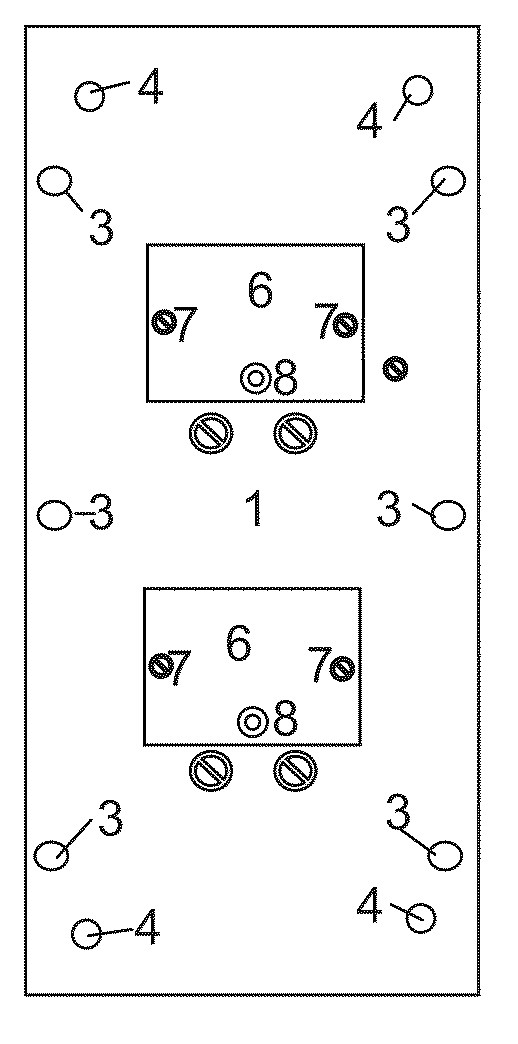
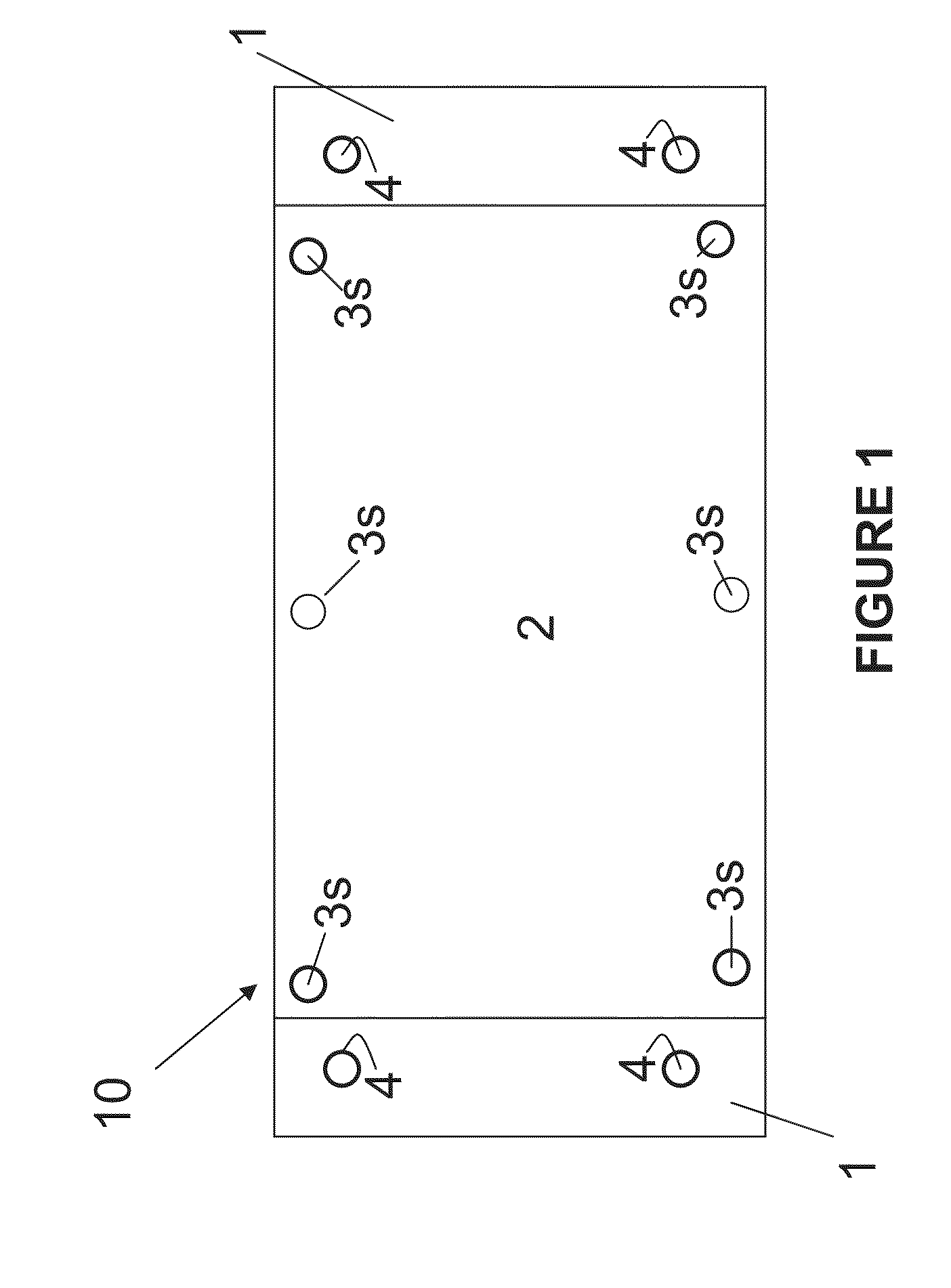
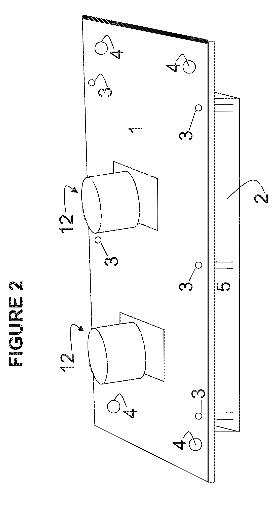
"The present invention is a new type of antenna array that is designed to transmit high power RF efficiently. It is low profile in construction, but maintains its ability to transmit high power RF. The antenna is supported in free space by metallic posts rather than by a dielectric material, which increases its efficiency. The antenna has a bandwidth of more than three times the bandwidth of a normal patch array at 5.8 GHz center frequency. It offers a low-profile, light-weight, and low-cost solution for high power microwave applications. The antenna's architecture is unique, reproducible, and affordable for manufacturing. It can be used for high power microwave applications and has a maximum achievable gain of (11.5 dBi and a bandwidth of (957 MHz -17% bandwidth) referenced to the center frequency of 5.8 GHz."

Problems solved by technology

As such, only 30 W is dissipated within the antenna structure, primarily due to ohmic losses.

Method used


Image

  • High efficiency and high power patch antenna and method of using
  • High efficiency and high power patch antenna and method of using
  • High efficiency and high power patch antenna and method of using

Examples


Embodiment Construction

[0045]The embodiments of the invention and the various features and advantageous details thereof are explained more fully with reference to the non-limiting embodiments that are illustrated in the accompanying drawings and detailed in the following description. It should be noted that the features illustrated in the drawings are not necessarily drawn to scale. Descriptions of well-known components and processing techniques are omitted so as to not unnecessarily obscure the embodiments of the invention. The examples used herein are intended merely to facilitate an understanding of ways in which the embodiments of the invention may be practiced and to further enable those of skilled in the art to practice the embodiments of the invention. Accordingly, the examples should not be construed as limiting the scope of the embodiments of the invention.

[0046]The terminology used herein is for the purpose of describing particular embodiments only and is not intended to limit the full scope of ...


PUM


Abstract

A patch antenna system and method comprising a base extending in a first plane; at least one patch mounted in a plane substantially parallel to the first plane; spaced from the base by at least one metallic post such that between the base and patch is substantially only gaseous fluid (which may be air). At least one power source may be operatively connected to the at least one patch for generation of electromagnetic waves at a center frequency of approximately 5.8 Gigahertz. The method of neutralizing unattended microwave devices comprises connecting a power source to a patch antenna and operating the patch antenna at a frequency in the range of approximately 3.89 to of 5.85 Gigahertz in the vicinity of a suspected unattended microwave device used to activate an explosive device to thereby jam any communication signal to the unattended microwave device and prevent the activation.

Description

STATEMENT OF GOVERNMENT INTEREST[0001]The invention described herein may be manufactured, used, and licensed by or for the United States Government.CROSS-REFERENCE TO RELATED APPLICATIONS[0002]This application claims priority under 35 U.S.C. §120 to U.S. patent application Ser. No. 12 / 178,771, filed on Jul. 29, 2008, which is hereby incorporated by reference as though fully rewritten herein.FIELD OF THE INVENTION[0003]This invention relates broadly to antennas and more particularly to high power antennas operable at high frequencies.BACKGROUND OF THE INVENTION[0004]An antenna is an element used for radiating or receiving electromagnetic waves. While antennas are available in numerous different shapes and sizes, they all operate according to the same basic principles of electromagnetics. According to Faraday's law, the induced electromotive force or emf in any closed circuit is equal to the time rate of change of the magnetic flux through the circuit. Electromotive force, emf, measur...

Claims


Application Information

Patent Timeline
Patent Type & Authority Patents(United States)
IPC IPC(8): H01Q1/38
CPCH01Q9/0407H01Q9/0421H01Q9/045H04K3/42H04K3/92H04K2203/16H04K2203/24H04K2203/32
Inventor LY, CANHHARRISON, ARTHUR C.
Owner US SEC THE ARMY THE
Learn More