
Motor

a motor and flange technology, applied in the field of motors, can solve the problems of difficult processing of not only one surface but also the other surface of the flange portion, the height of such a motor can only be reduced to a limited degree, and the deformation is more significant, so as to avoid an increase in production costs and facilitate processing. , the effect of not increasing the rotational load

Inactive Publication Date: 2007-10-23
ALPHANA TECH CO LTD
View PDF4 Cites 6 Cited by
  • Summary
  • Abstract
  • Description
  • Claims
  • Application Information

AI Technical Summary

Benefits of technology

[0016]The present invention has been made in view of the above disadvantages and the objective thereof is a provision of a motor that includes a dynamic pressure bearing whose constituting parts can be easily processed, and has a high reliability, a low-profile construction, and a low rotational load.
[0021]According to the present invention, constituting parts and components are easily processed, thereby avoiding an increase in production costs; a rotational load is not increased; and a floating amount of the rotor is stabilized, thereby leading to a higher reliability; and a low-profile construction is realized.

Problems solved by technology

However, it is very difficult to process not only one surface but also the other surface of the flange portion paying much attention to degree of parallelization or the like, because the portion can be significantly deformed by a load applied thereon.
Especially, when the flange portion is thin, the deformation is more significant and, in the end, a height of such a motor can only be reduced to a limited degree.
However, it is extremely difficult to control a degree of magnetization at the same time as taking account of magnetic characteristic variations that occur in a sintering process of magnet production.
Moreover, since variations in dimension are particularly larger in a magnet made of a sintered material than in other members and components made of metal, a distance between the magnet and the stator yoke varies and as a result magnetic attractive force cannot be stabilized, which makes it difficult to precisely keep the rotor floated.
In addition, there exists a disadvantage in that an eddy current occurs in the stator yoke, thereby producing a rotational load.

Method used


Image

  • Motor
  • Motor
  • Motor

Examples


Embodiment Construction

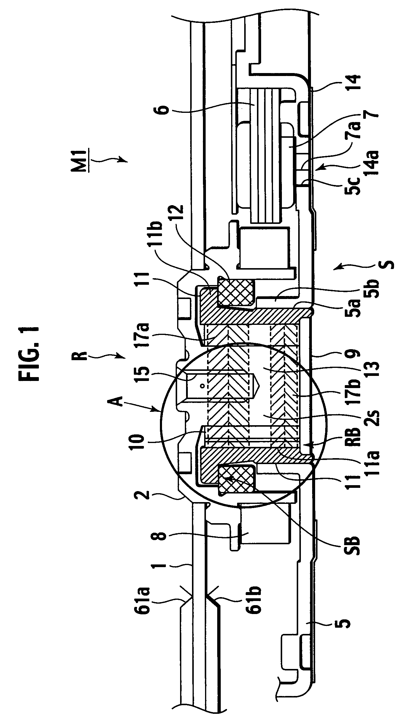
[0031]Referring to FIGS. 1 to 8, a motor M1 according to one of preferred embodiments of the present invention will be described. The motor in this embodiment is a disc-driving motor that has loaded a 1 inch magnetic recording disc and is preferably used in a disc drive apparatus. The motor is capable of rotating 7200 rotations per minute (rpm) during operation.

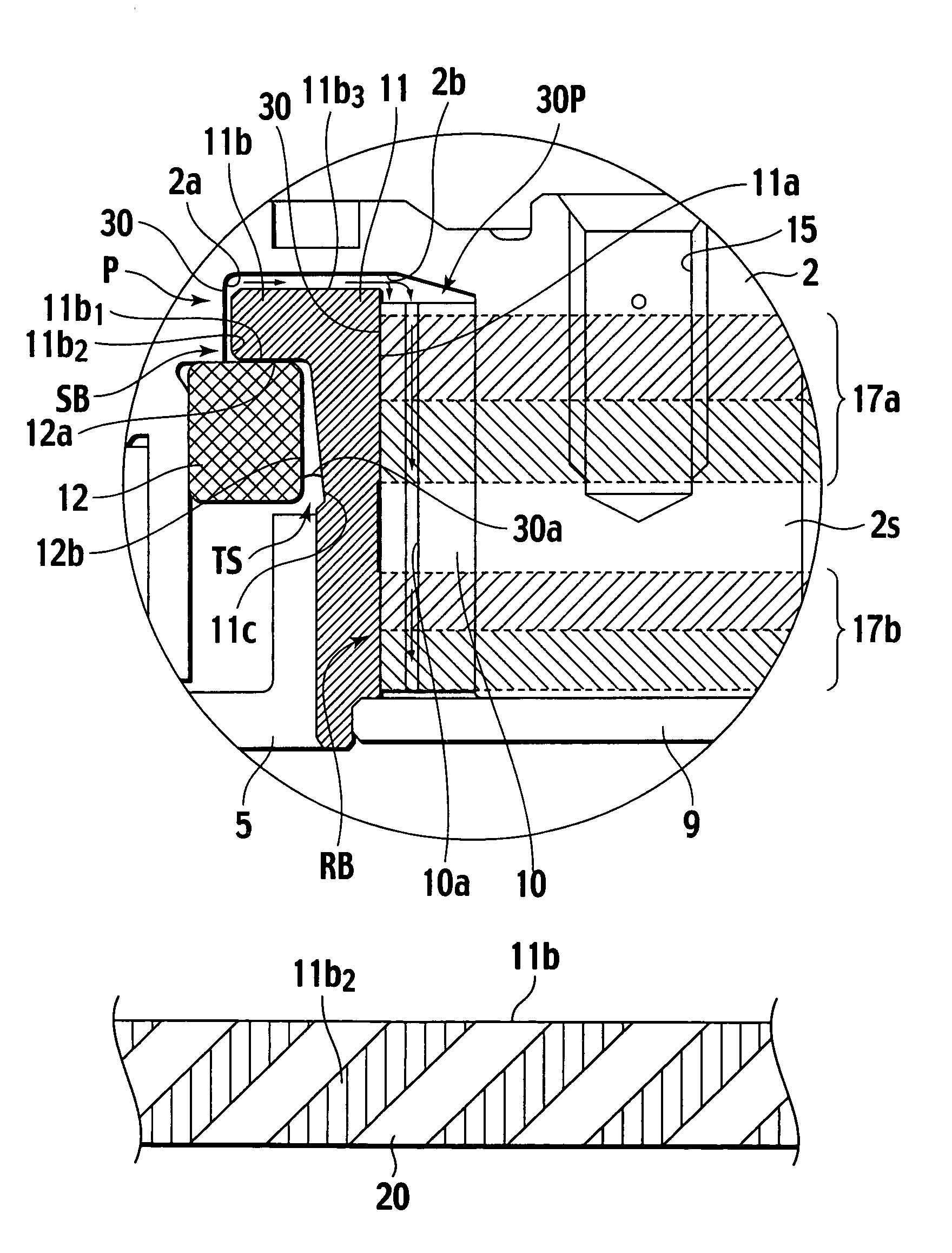
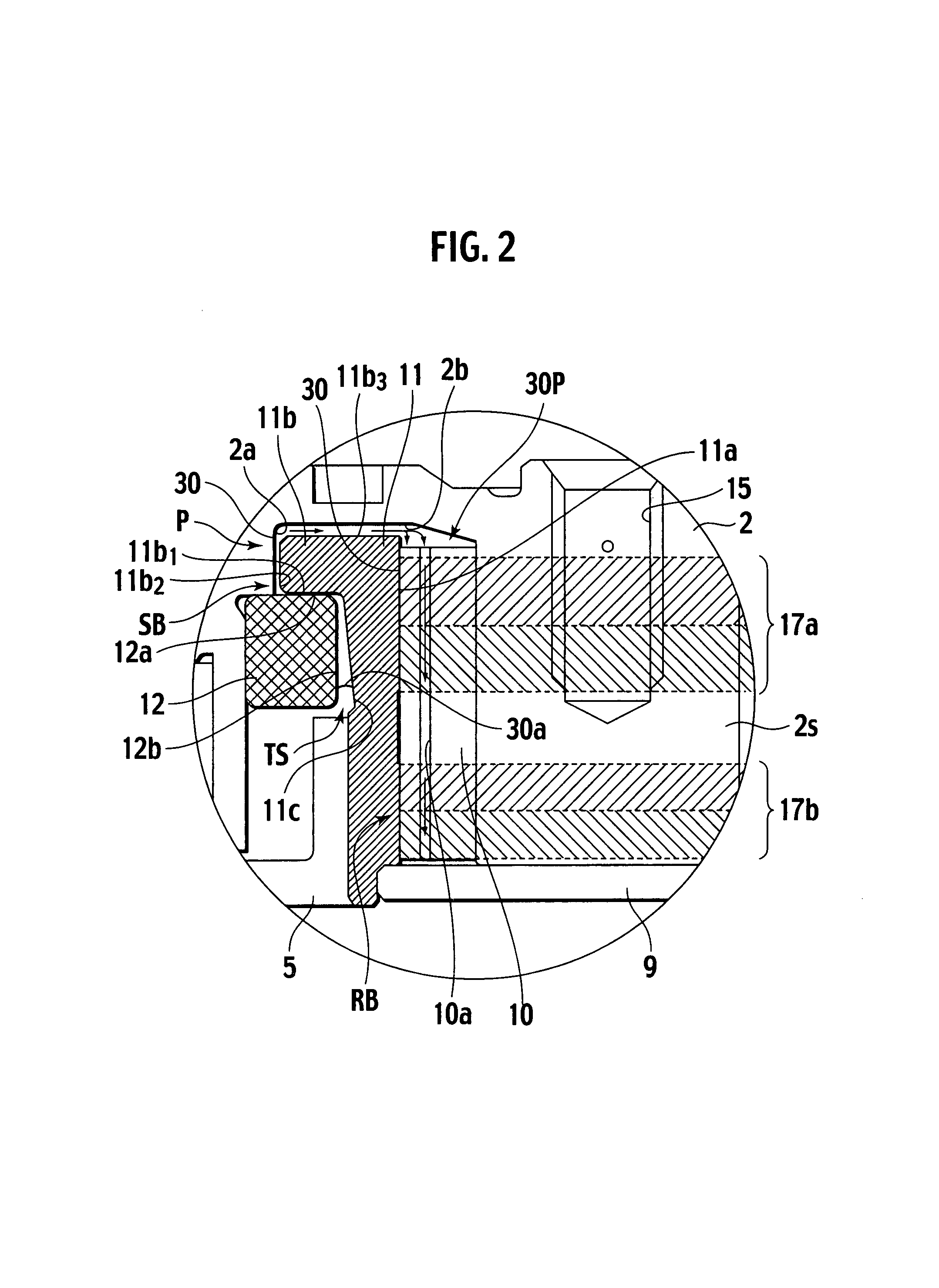
[0032]As illustrated in FIGS. 1 and 2, the motor M1 is composed of a rotor R having a hub on which a magnetic recording disc 1 is loaded, and a stator S having a sleeve 11. The rotor R is supported rotatably in relation to the stator S by a thrust dynamic pressure bearing portion SB and a radial dynamic pressure bearing portion RB (referred to as a dynamic pressure bearing B hereinafter, as the case may be).

[0033]First, the stator S will be detailed. The stator S has a motor base 5, a cylindrical sleeve 11 secured on the motor base 5, and a core 6. The core 6 is substantially annular shaped having a cut-away portion L that ma...


PUM


Abstract

One preferred embodiment of the present invention provides a motor composed at least of a stator, a rotor, and a dynamic pressure bearing having a thrust dynamic pressure bearing portion and a radial dynamic pressure bearing portion to support the rotor rotatably in relation to the stator, comprising lubrication fluid being filled in a lubrication fluid filled portion connecting said thrust dynamic pressure bearing portion with said radial dynamic pressure bearing portion and being used in common by said thrust dynamic pressure bearing portion and said radial dynamic pressure bearing portion, and a pump-in dynamic pressure generation portion being disposed between said thrust dynamic pressure bearing portion and said radial dynamic pressure bearing portion so as to generate pressure that causes the lubrication fluid to move toward said radial dynamic pressure bearing portion.

Description

BACKGROUND OF THE INVENTION[0001]1. Field of the Invention[0002]The present invention relates to a motor equipped with a dynamic pressure bearing.[0003]2. Description of the Related Art[0004]In a disc reading and writing apparatus, a motor equipped with a dynamic pressure fluid bearing has become in general use as a disc driving motor. This is because a dynamic pressure fluid bearing has a unique characteristic of high reliability and longevity, which is favorable for use in such an apparatus.[0005]By the way, there has been a strong demand for a thin-model disc drive apparatus from the market and thus a thin motor has been required to be equipped therein.[0006]To meet such a demand, there have been disclosed various kinds of thin-model disc drive apparatuses equipped with a thrust dynamic pressure bearing disposed coaxially around a radial dynamic pressure bearing in Japanese Patent Application Laid-open Publications Nos. 2001-65552 (referred to as a patent document 1, hereinafter)...

Claims


Application Information

Patent Timeline
Patent Type & Authority Patents(United States)
IPC IPC(8): H02K5/16
CPCF16C17/045H02K7/085F16C33/107F16C17/10F16C2370/12
Inventor KODAMA, MITSUO
Owner ALPHANA TECH CO LTD
Learn More