Cartridge loading mechanism

a magnetic tape drive and loading mechanism technology, applied in the direction of data recording, record carrier guidance, instruments, etc., can solve the problems of deteriorating surface condition of the sliding contact portion of the cartridge, affecting the operation of the magnetic tape drive, and requiring a large amount of time to access the desired data, so as to achieve the effect of improving operability and reliability

Inactive Publication Date: 2007-02-27
FUJITSU LTD
View PDF4 Cites 0 Cited by
  • Summary
  • Abstract
  • Description
  • Claims
  • Application Information

AI Technical Summary

Benefits of technology

[0014]It is therefore an object of the present invention to provide a cartridge loading mechanism improved in operability and reliability.

Problems solved by technology

On the other hand, a magnetic tape drive may have a disadvantage such that much time is required for the access to desired data in some case.
(1) In inserting the cartridge into the carrier, the reaction force of the shutter is generated. Accordingly, an operator (or a handling robot in a library unit) is required to generate a cartridge inserting force greater than the reaction force of the shutter.
(2) In inserting the cartridge into the carrier, the reaction force of the hook is generated. Accordingly, the operator is required to generate a cartridge inserting force greater than the reaction force of the hook.
(3) Also in ejecting the cartridge from the carrier, the reaction force of the hook is generated. Accordingly, the operator is required to generate a cartridge ejecting force greater than the reaction force of the hook.
(4) The cartridge always comes into strong sliding contact with the hook, so that a sliding contact portion of the cartridge to the hook is worn. Accordingly, the surface condition of this sliding contact portion of the cartridge is deteriorated or wear particles are generated from the cartridge. As a result, there is a possibility that the sliding friction between the hook and the cartridge may be increased during the cartridge inserting operation by the operator and that the cartridge cannot be normally inserted into the carrier.
(5) Also during the cartridge ejecting (removing) operation by the operator, the sliding friction between the hook and the cartridge may be increased to cause a problem that the cartridge cannot be ejected from the carrier.

Method used


Image

  • Cartridge loading mechanism
  • Cartridge loading mechanism
  • Cartridge loading mechanism

Examples


Embodiment Construction

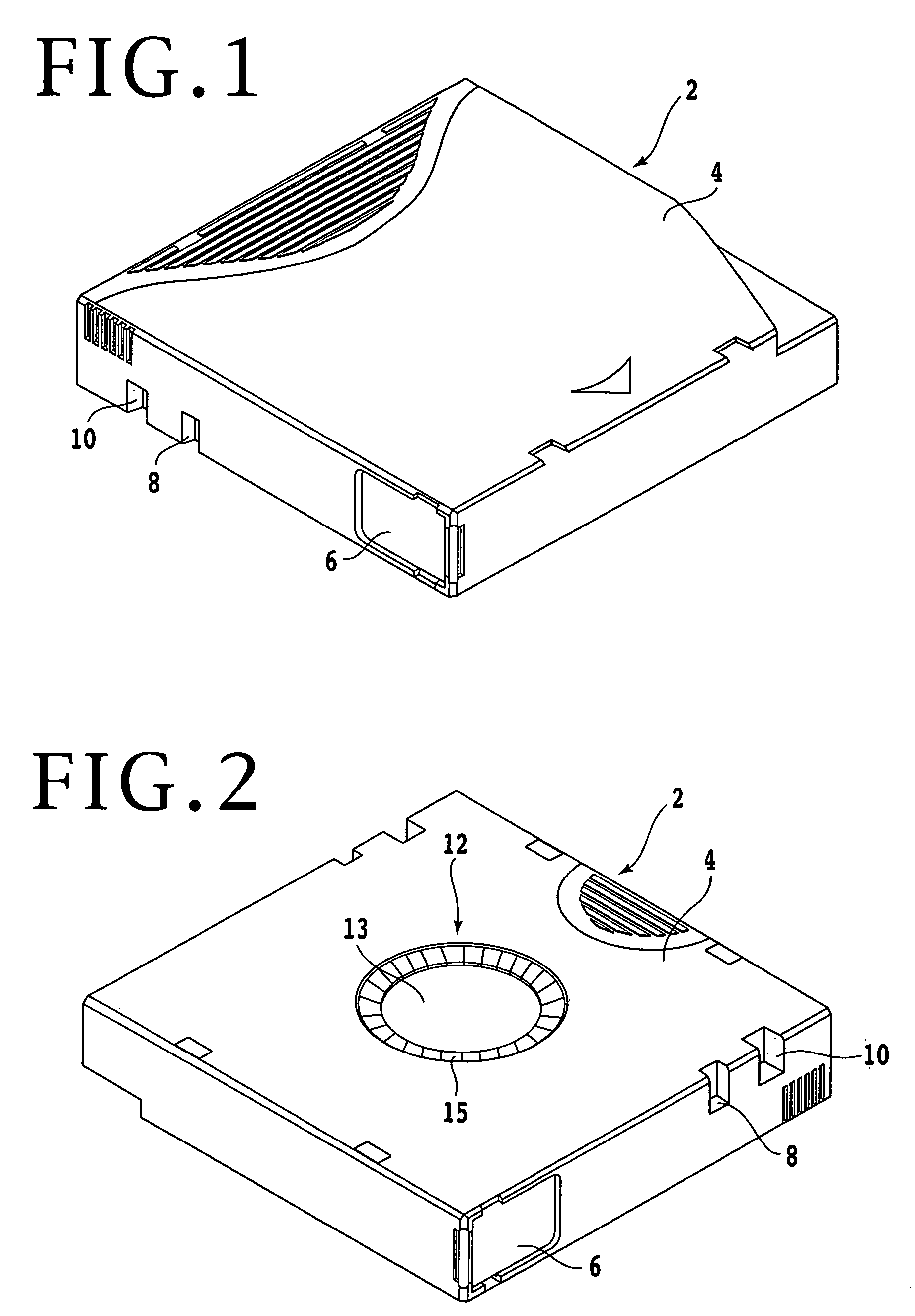
[0043]Referring to FIG. 1, there is shown a perspective view of an LTO type magnetic tape cartridge 2. FIG. 2 is another perspective view of the magnetic tape cartridge 2, showing the lower side thereof. The magnetic tape cartridge 2 has a cartridge casing 4 accommodating a magnetic tape wound around a cartridge reel. The magnetic tape cartridge 2 has one side surface formed at its front end with a shutter (lid) 6 normally biased in its closing direction. This one side surface of the magnetic tape cartridge 2 is further formed with two notches 8 and 10 exposed to the lower surface of the magnetic tape cartridge 2. As shown in FIG. 2, the magnetic tape cartridge 2 has a chucking mechanism 12 composed of a magnetic member 13 such as an iron member and an annular gear 15. The chucking mechanism 12 is connected to the cartridge reel accommodated in the cartridge casing 4.

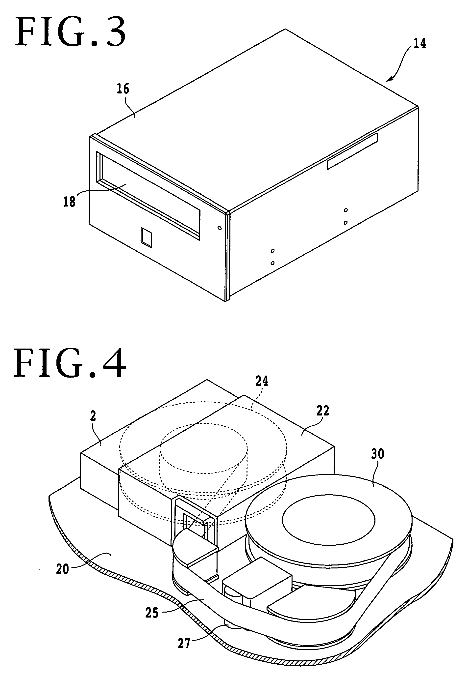
[0044]FIG. 3 is a perspective view of a magnetic tape drive 14, showing the external appearance thereof, and FIG. 4 i...


PUM

PropertyMeasurementUnit
timeaaaaaaaaaa
resilientaaaaaaaaaa
reaction forceaaaaaaaaaa

Abstract

A cartridge loading mechanism including a carrier movable between a first position where a magnetic tape cartridge having an openable shutter and a notch is inserted into the carrier and a second position where the cartridge is mounted onto a reel motor, and a shutter opening mechanism fixed to a base of a magnetic tape drive and having an engaging portion adapted to engage the shutter of the cartridge to open the shutter. The loading mechanism further includes a leaf spring mounted on the carrier and having a hook adapted to engage the notch of the cartridge, and a driving mechanism for moving the carrier between the first position and the second position. After the hook of the leaf spring comes into engagement with the notch of the cartridge at a third position during the movement of the carrier from the first position to the second position, the engaging portion of the shutter opening mechanism starts to engage the shutter of the cartridge.

Description

[0001]This is a continuation of PCT International Application NO. PCT / JP03 / 005959, filed May 13, 2003, which was not published in English.BACKGROUND OF THE INVENTION[0002]1. Field of the Invention[0003]The present invention relates generally to an autoloading mechanism for a magnetic tape drive using a magnetic tape cartridge, and more particularly to an autoloading mechanism for a magnetic tape drive using an LTO (Linear Tape Open) medium.[0004]2. Description of the Related Art[0005]At present, a magnetic disk drive, optical disk drive, magnetic tape drive, etc. are used as an external storage device for a computer. A disk drive such as a magnetic disk drive and an optical disk drive can provide easy access to desired data, so that the research and development for such a disk drive are increasingly conducted and technological innovation on increasing a storage capacity, for example, is remarkable. On the other hand, a magnetic tape drive may have a disadvantage such that much time ...

Claims


Application Information

Patent Timeline
Patent Type & Authority Patents(United States)
IPC IPC(8): G11B15/675G11B15/67G11B15/68
CPCG11B15/67G11B15/67557G11B15/67544G11B15/672
Inventor YAMAKAWA, KENGO
Owner FUJITSU LTD
Why Eureka
Try Eureka