Object detection

Inactive Publication Date: 2007-02-27
COLUMBIA PEAK VENTURES LLC
View PDF118 Cites 50 Cited by
  • Summary
  • Abstract
  • Description
  • Claims
  • Application Information

AI Technical Summary

Benefits of technology

[0011]As explained above, γref can be calculated once and T can be chosen once at the time when a system embodying the present invention is setup or initialized and then both γref and T can be used as constants throughout the operation of the system. Alternatively, the reference image could be updated periodically and new values for γref and T calculated. Updating the reference image periodically would allow for embodiments of the present invention to account for changes in the environment, such as a slight deterioration of the background pattern over time.
[0012]The present invention can be embodied in a monitoring system able to detect the intrusion of people (or other objects) into a user-defined safety zone. The present invention provides superior methods for distinguishing between objects actually entering the user-defined area and shadows caused to be cast onto the user-defined area by changes in lighting or objects moving near the user-defined area.

Problems solved by technology

Second, live images containing shadows instead of objects tend to not produce any complements or inverse images in a difference image.

Method used


Image

  • Object detection
  • Object detection
  • Object detection

Examples


Embodiment Construction

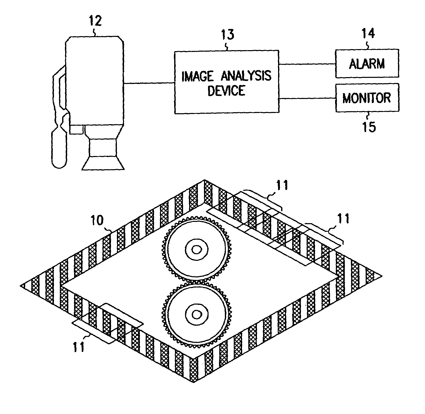
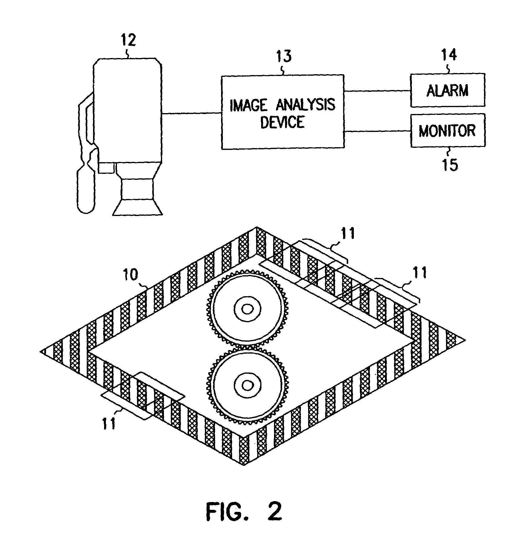
[0017]Unless indicated otherwise, the term “image” used in the current specification will refer to a digitized image having an array or vector of numbers representing brightness (that is, luminance intensity) levels. Each brightness level ranges from 0 (the darkest) to Imax (the brightest). In embodiments of the present invention, the actual numerical intensity levels may range from 0 to 1.0 or from 0 (00000000 in binary notation) to 255 (11111111 in binary notation), for example, depending on the specific equipment utilized. Equipment for digitizing images and converting to arrays of brightness levels is well known in the art. The numerical brightness levels are frequently referred to as pixels.

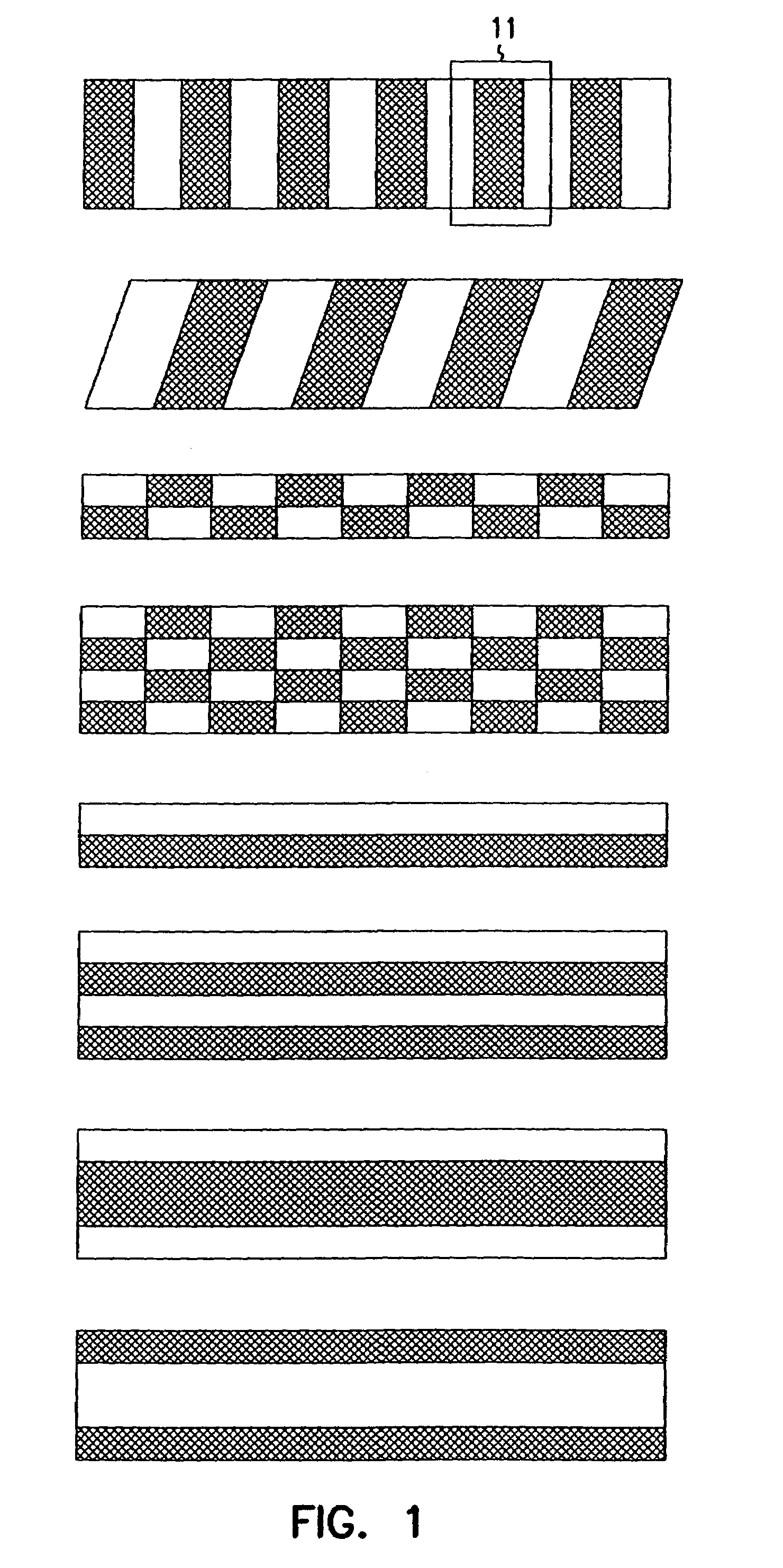
[0018]According to the present invention, each captured image of the monitored area is divided up into portions or segments. These portions or segments are referred to as mask windows. The size of each mask window is chosen so that it is no bigger than the approximate size of the smallest ob...


PUM


Abstract

A method for object detection that utilizes a patterned background. Patterned backgrounds are chosen such that each reference image analyzed will have both light and dark pixels. The method calculates the difference between the expected value for the light pixels and the expected value of the dark pixels in the reference image. This difference is used to chose a threshold value. The difference in expected values for the corresponding pixels in a live image is calculated and compared to the threshold value. If the difference in expected values of the live image are less than the threshold value, object detection is indicated.

Description

[0001]This application is a continuation of U.S. Patent Application Ser. No. 09 / 716,002, filed Nov. 17, 2000, entitled OBJECT DETECTION, issued as U.S. Pat. No. 6,711,279 on Mar. 23, 2004.FIELD OF THE INVENTION[0002]The present invention relates to object detection. More specifically, the present invention relates to the detection of objects in a user-defined area having a patterned background.BACKGROUND OF THE INVENTION[0003]Motion detection and object detection systems are known in the art. Frequently, such systems are used to monitor a user-defined area to detect whenever an object enters the area. The equipment needed to implement an object detection system is well known in the art. Such systems comprise an imaging device (typically a video camera) capable of capturing an image of the monitored area and a device for digitizing the captured images. The digitized images are then analyzed in an attempt to detect whether an object has entered the monitored area. There exist many dif...

Claims


Application Information

Patent Timeline
Patent Type & Authority Patents(United States)
IPC IPC(8): G06K9/00G06K9/20H04N9/47H04N7/18G08B13/194
CPCG06K9/00771G08B13/19606G08B13/19604G08B13/19602G06V20/52
Inventor HAMZA, RIDHA M.COFER, DARREN DUANE
Owner COLUMBIA PEAK VENTURES LLC
Why Eureka
Try Eureka