Power plant

a power plant and condenser technology, applied in the direction of liquid degasification, water feed control, separation process, etc., can solve the problems of reducing heat generation efficiency, increasing the pressure in the condenser in summer, and not using a lower-temperature heat source, so as to reduce the amount of working medium released to the outside of the plant, reduce the condenser condensing performance, and prevent the effect of power generation efficiency reduction

Active Publication Date: 2014-07-10
FUJI ELECTRIC CO LTD
View PDF8 Cites 3 Cited by
  • Summary
  • Abstract
  • Description
  • Claims
  • Application Information

AI Technical Summary

Benefits of technology

[0031]According to the present invention, the pressure threshold value obtained by adding the margin value to the saturated vapor pressure value of the medium calculated based on the temperature in a liquid phase portion of the gas retaining portion and the pressure value of a gas phase portion of the gas retaining portion are compared with each other, thereby intrusion of an air is detected. Therefore, it is possible to automatically detect the intrusion of the air into the medium flow path of the power plant. Moreover, the amount of the working medium released to the outside of the plant can be reduced. Also, it is possible to prevent reduction in the power generation efficiency caused by a lowered condensing performance of the condenser because of intrusion of an air not condensed by the condenser into the medium.

Problems solved by technology

Thus, there is a problem that it cannot use a lower-temperature heat source.
Patent Literature 3 described above has problems that the pressure in the condenser increases in summer and the heat generation efficiency is reduced, because the concentration of the low boiling point medium is determined to provide a pressure around the atmospheric pressure as the lowest pressure which can be generated in the condenser in winter.
Thus, there is a problem that an outflow of the medium increases because the air removing operation is performed more than necessary.

Method used


Image

  • Power plant
  • Power plant
  • Power plant

Examples


Embodiment Construction

[0039]Embodiments of the present invention will be described below based on the drawings. First, description is now made to an example of the embodiment of the present invention based on FIGS. 1 to 6.

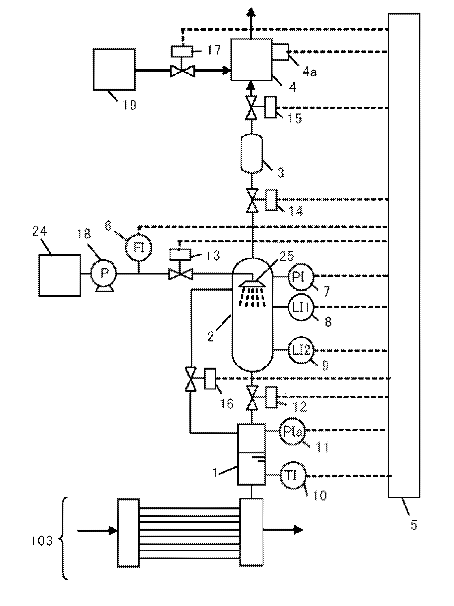
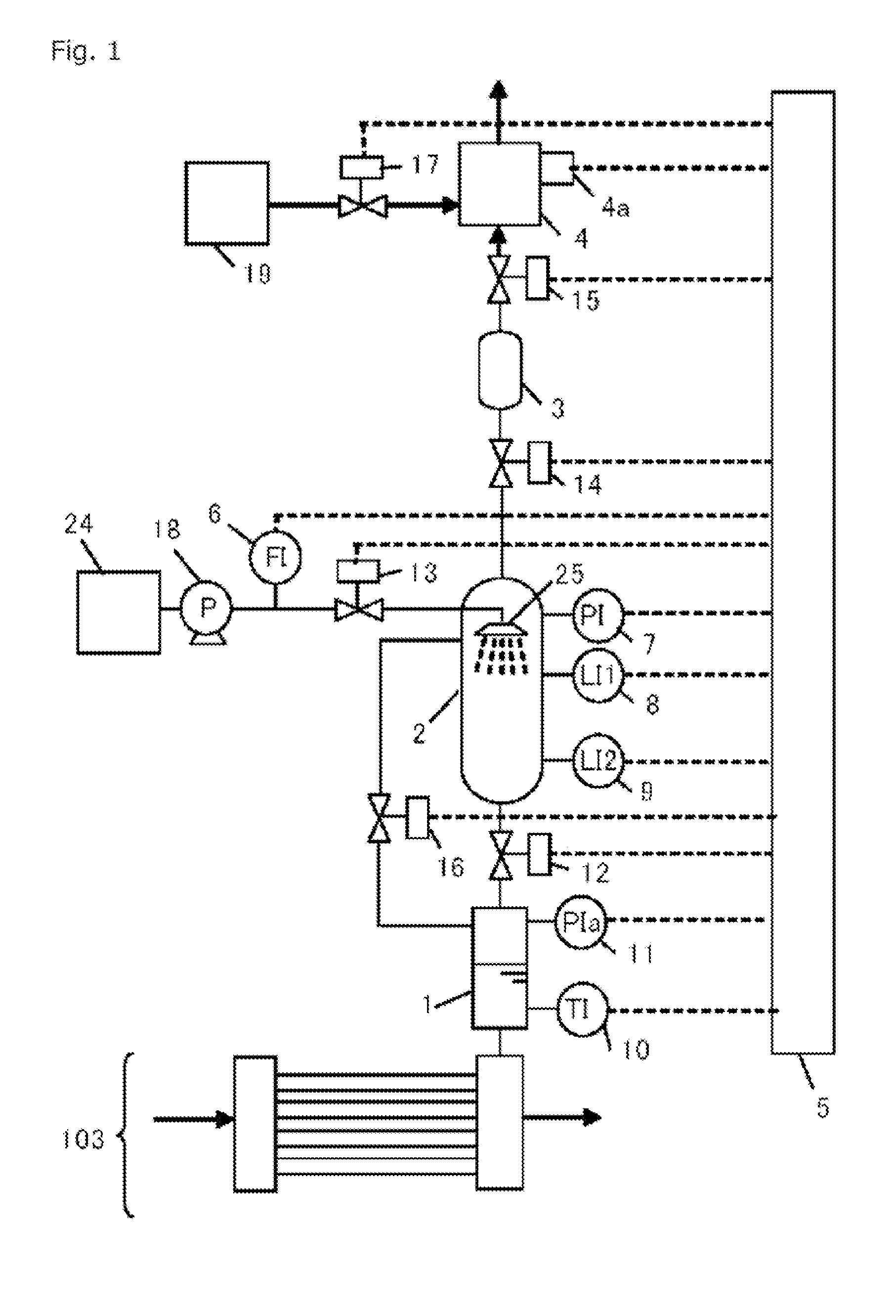
[0040]FIG. 1 is a diagram showing the constitution of an intruding air removing device according to an example of the present invention. A condenser 103 in FIG. 1 corresponds to the condenser 103 in FIG. 7. A gas retaining portion 1 is connected to an upper portion of an outlet-side collector of the condenser 103. An air intruding into a medium is collected into the gas retaining portion 1 via the outlet-side collector. To the gas retaining portion 1, a thermometer 10 for measuring the temperature in the gas retaining portion 1 and a pressure gauge 11 for measuring the pressure in the gas retaining portion 1 are provided.

[0041]A first chamber 2 is connected to the gas retaining portion 1 with a pipe via a valve 12. Moreover, a pipe is provided for connecting an upper portion of the firs...


PUM

PropertyMeasurementUnit
temperatureaaaaaaaaaa

Abstract

A binary power generation device is equipped with the flow path of a medium circulating through a heat exchanger, a turbine, a condenser, and a pump. A method for removing air that has intruded into the flow path of the medium includes: an air intrusion detection step of calculating, based on the pressure and temperature of a gas retaining portion communicatively connected to the flow path of the medium, a pressure threshold value obtained by adding the saturated vapor pressure of the medium and a margin value and of detecting, by comparing the pressure of a gas phase portion with the pressure threshold value, that air has intruded into the medium; a medium liquefaction step of producing a gas by pressurizing a mixed gas of the medium and air to reduce the amount of the medium in the mixed gas; and an exhaust step of exhausting the gas.

Description

TECHNICAL FIELD[0001]The present invention relates to a power plant using a medium having a lower boiling point than water as a working medium, equipped with an air removing device which removes an air intruding into the working medium.BACKGROUND ART[0002]A power plant, using a low boiling point medium, for recovering heat energy from a low-temperature heat source which has not been utilized in conventional geothermal power generation using a steam turbine and for generating a power has attracted special attention as an energy recovery device recently (see Patent Literature 1).[0003]FIG. 7 shows a basic system diagram of a conventional power plant using a low boiling point medium. This power plant exchanges heat between a medium having a lower boiling point than water and a heat source by a vaporizer 100 to evaporate this medium, rotates a turbine 101 by this medium vapor, and operates an electric generator 102 by the rotational force, thereby obtaining a power. The medium exiting f...

Claims


Application Information

Patent Timeline
Patent Type & Authority Applications(United States)
IPC IPC(8): F01K25/08F01K19/00F01K9/02
CPCF01K9/00F01K9/023F01K19/00F01K25/08
Inventor MYOGAN, ICHIROSHIBATA, HIROAKIKAWAHARA, YOSHITAKAOSAWA, ISAMUKUBOTA, KOKAN
Owner FUJI ELECTRIC CO LTD
Why Eureka
Try Eureka