Fuel battery cell stack and fuel battery

A fuel cell unit, fuel cell technology, applied in fuel cell grouping, fuel cells, fuel cell additives, etc., can solve the problems of reduced power generation efficiency and uneven temperature distribution, achieve high power generation performance, and restrain the reduction of power generation efficiency , the effect of improving reliability

Inactive Publication Date: 2009-08-26
KYOCERA CORP
View PDF1 Cites 4 Cited by
  • Summary
  • Abstract
  • Description
  • Claims
  • Application Information

AI Technical Summary

Problems solved by technology

[0009] Therefore, the temperature at the central part in the direction in which the fuel cells are arranged becomes high, and the temperature at the end parts in the direction in which the fuel cells are arranged becomes low. Therefore, as a fuel cell group, the temperature in the direction in which the fuel cells are arranged Distribution becomes uneven (Yamagata), power generation efficiency may decrease

Method used


Image

  • Fuel battery cell stack and fuel battery
  • Fuel battery cell stack and fuel battery
  • Fuel battery cell stack and fuel battery

Examples


Embodiment Construction

[0052] Hereinafter, preferred embodiments of the present invention will be described in detail with reference to the drawings.

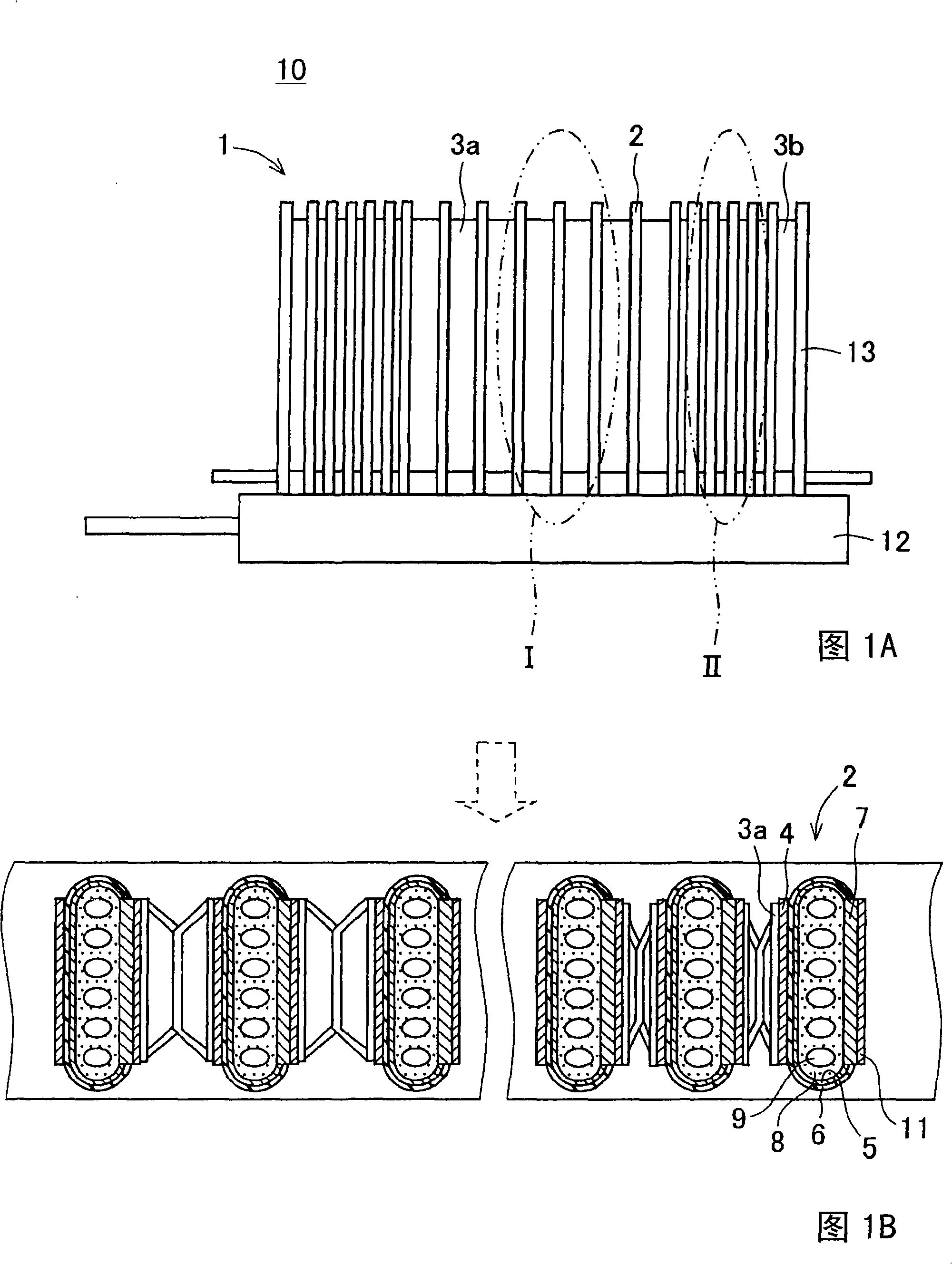
[0053] Figure 1A and Figure 1B represents a fuel cell stack device 10 having a fuel cell stack 1, Figure 1A is a side view schematically showing the fuel cell stack device 10, Figure 1B yes Figure 1A A partially enlarged top view of the fuel cell stack device 10 of . and also, Figure 1B the left side of Figure 1A An enlarged top view of part I, Figure 1B the right side of Figure 1A An enlarged top view of part II. In addition, the same code|symbol is attached|subjected about the same component, and it is the same below. Furthermore, in Figure 1B In , the arrow indicated by the dotted line indicates the flow direction of the oxygen-containing gas.

[0054] Here, the fuel cell stack device 10 of the present invention includes a fuel cell stack 1 and a manifold 12 . In the fuel cell stack 1 of the present invention, a plurality of ...


PUM

PropertyMeasurementUnit
electrical conductivityaaaaaaaaaa
thicknessaaaaaaaaaa

Abstract

Provided is a fuel battery cell stack capable of improving generation efficiency by uniformizing the temperature distribution I n the arrangement direction of the fuel battery cells in a fuel battery cell stack where a plurality of fuel battery cells are aligned. Each of the fuel battery cells (2) is formed by a fuel cell side electrode layer (5), a solid state electrolyte layer (6), and air side electrode layer (4) which are successively layered on a support substrate (8). The fuel battery cells (2) are electrically connected in series to one another in the fuel battery cell stack (1). The interval between fuel battery cells (2) arranged at the center portion in the arrangement direction of the fuel battery cells (2) is set greater than the interval between the fuel battery cells (2) arranged at the end portion side in the arrangement direction of the fuel battery cells (2). This can substantially uniformize the temperature distribution of the fuel battery cell stack (1).

Description

technical field [0001] The present invention relates to a fuel cell group in which a plurality of fuel cell cells are arranged, and a fuel cell in which a fuel cell group is accommodated. Background technique [0002] In recent years, as a next-generation energy source, a fuel cell in which a fuel cell group is housed in a container is proposed, and the fuel cell group has a large number of fuel cell cells that can obtain electric power using fuel gas and air (oxygen-containing gas). , and connect them electrically in series. [0003] Hydrogen is used as a fuel gas used for power generation in the fuel cell, the hydrogen is brought into contact with the fuel-side electrode layer of the fuel cell, and the oxygen-containing gas is brought into contact with the air-side electrode layer of the fuel cell to generate a predetermined electrode reaction, Power generation is thereby performed. [0004] Here, various fuel cell groups in which a plurality of fuel cells are arranged h...

Claims


Application Information

Patent Timeline
Patent Type & Authority Applications(China)
IPC IPC(8): H01M8/24H01M8/02H01M8/12
CPCH01M8/04067H01M8/0297H01M8/04007H01M8/249Y02E60/50Y02E60/525H01M2008/1293H01M8/2425H01M8/0258H01M8/0271H01M8/241H01M8/2465H01M8/2457H01M8/2483
Inventor 小野孝
Owner KYOCERA CORP
Why Eureka
Try Eureka