Solar Cell Panel

a solar cell and panel technology, applied in the field of solar cell panels, can solve the problems of single crystal silicon, limited design, and marred views, and achieve the effect of not lowering the power generation efficiency of solar cells and excellent decoration

Inactive Publication Date: 2008-12-11
TOHOKU UNIV
View PDF9 Cites 4 Cited by
  • Summary
  • Abstract
  • Description
  • Claims
  • Application Information

AI Technical Summary

Benefits of technology

[0013]According to this invention, since the color is developed based on the solar energy of the infrared components that do not contribute to the power generating operation of the solar cell, the power generation efficiency of the solar cell is not lowered.
[0014]Further, according to this invention, since various light-emitting panels can be realized, there is obtained an effect also excellent in terms of decoration as compared with the conventional black panels.

Problems solved by technology

However, the solar cell panels made of amorphous silicon or single-crystal silicon are normally black on the whole and are thus limited in design.
Therefore, when they are arranged on the roofs of general houses being conspicuous places, and so on, there are instances where views are marred in appearance.
As a result, there is a cause for delaying the spread of solar cell panels.

Method used


Image

  • Solar Cell Panel
  • Solar Cell Panel
  • Solar Cell Panel

Examples


example 1

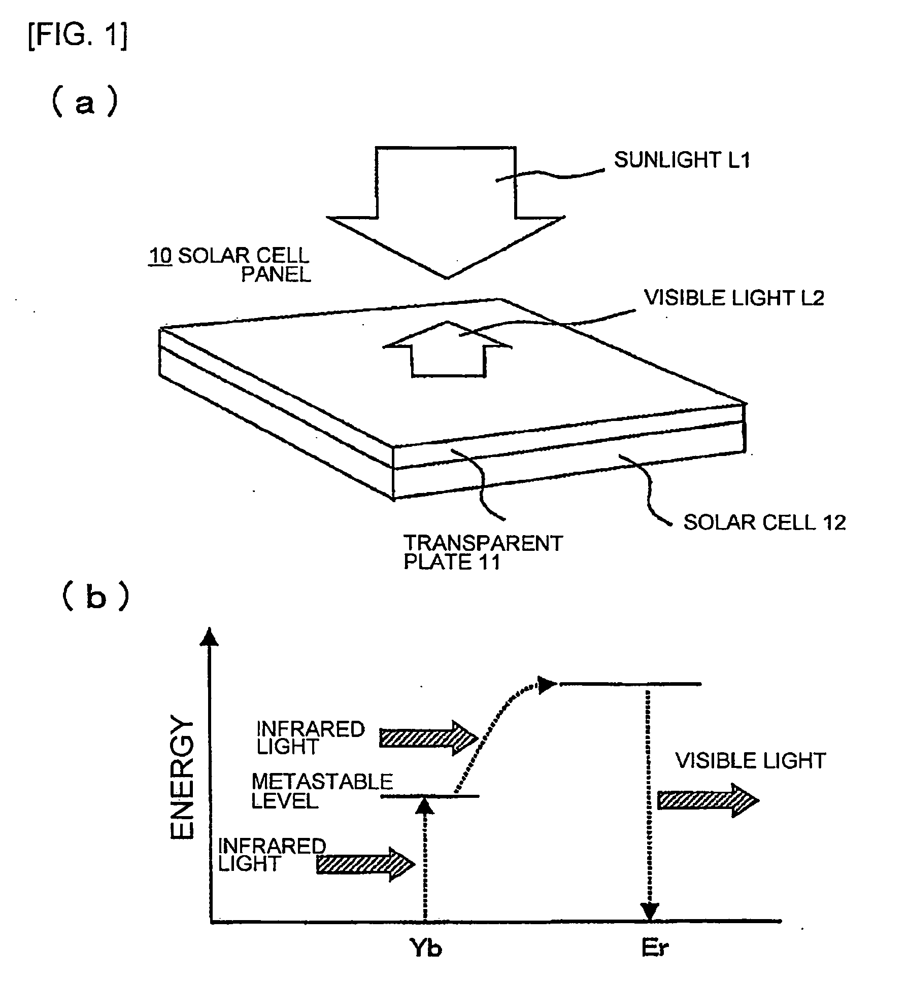
[0031]The first example of this invention will be described using FIGS. 1, (a) and (b). FIGS. 1, (a) and (b) are explanatory diagrams showing an outline of a solar cell panel 10 being the first example of this invention and an operation principle thereof. The shown solar cell panel 10 comprises a solar cell 12 using amorphous silicon and a transparent plate 11 having a thickness of about 5 mm and bonded to the solar cell 12. The transparent plate 11 is made of Pyrex (registered trademark) glass in which ytterbium (Yb) and erbium (Er) are doped as two kinds of lanthanoid series atoms (also including ionized atoms).

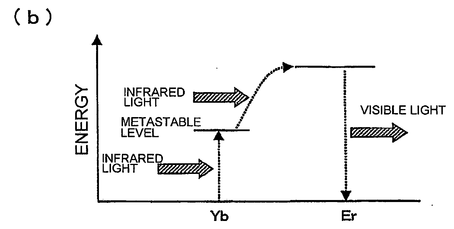
[0032]Ytterbium (Yb) has the property of absorbing photons of infrared light having a wavelength near 1000 nm and, when sunlight L1 is irradiated, it is excited to a metastable state by infrared components included therein. Since this level is relatively long, Ytterbium (Yb) can further absorb photons of the infrared light and thus further excited to a higher level correspo...

example 2

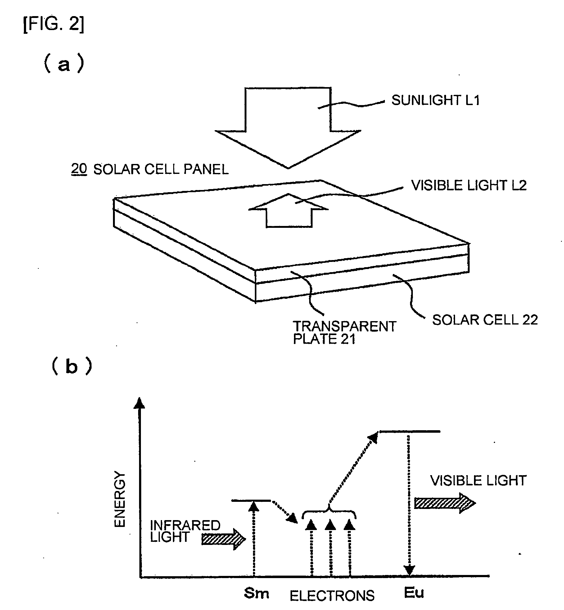
[0034]A solar cell panel according to the second example of this invention will be described using FIGS. 2, (a) and (b). FIG. 2, (a) is a perspective view showing an outline of a solar cell panel 20 and FIG. 2, (b) is a diagram for explaining an operation principle thereof. The shown solar cell panel 20 comprises a solar cell 22 using single-crystal silicon and a transparent plate 21 bonded to the solar cell 22. The shown transparent plate 21 is made of soda glass in which samarium (Sm) and europium (Eu) are doped as two kinds of lanthanoid series atoms.

[0035]Herein, the principle of the solar cell panel according to this example will be explained. When sunlight L1 is applied to the transparent plate 21, electrons having energy are produced by samarium (Sm) absorbing infrared light included in the sunlight L1, so that visible light L2 is generated upon recombination of europium (Eu) with the electrons. In this manner, the solar cell panel 20 is observed to be colored. In this case, ...


PUM


Abstract

Generally, solar cell panels are black, being inferior in design. An object of the invention is to provide a transparent plate which develops color without lowering power generation efficiency; and a solar cell panel which uses such transparent plate. A solar cell panel according to the invention has a construction such that the solar cell is covered by a transparent plate which is characterized by absorbing infrared light and emitting visible light. Since the transparent plate develops color by using infrared light which does not contribute to power generation, there is obtained a solar cell panel which is superior in the viewpoint of decoration without lowering the power generation efficiency of solar cells.

Description

TECHNICAL FIELD[0001]This invention relates to a structure of a solar cell panel and a transparent plate for use in the solar cell panel.BACKGROUND ART[0002]Generally, solar cell panels made of amorphous silicon or single-crystal silicon efficiently absorb the sunlight and, therefore, power generation efficiency (i.e. the ratio of the electric power generated by a solar cell relative to all the power radiated by the sunlight) often exceeds 20%. However, the solar cell panels made of amorphous silicon or single-crystal silicon are normally black on the whole and are thus limited in design. Therefore, when they are arranged on the roofs of general houses being conspicuous places, and so on, there are instances where views are marred in appearance. As a result, there is a cause for delaying the spread of solar cell panels.[0003]On the other hand, there have conventionally been proposed various attempts to color solar cell panels. For example, Japanese Unexamined Patent Application Publ...

Claims


Application Information

Patent Timeline
Patent Type & Authority Applications(United States)
IPC IPC(8): H01L31/042
CPCH01L31/02168Y02E10/52H01L31/055
Inventor OHMI, TADAHIROMORIMOTO, AKIHIROTAKEHISA, KIWAMU
Owner TOHOKU UNIV
Why Eureka
Try Eureka