Integrated coal gasification combined cycle facility

a gasification cycle and integrated technology, applied in steam generation plants, turbine/propulsion fuel heating, and preparation of lump/pulverulent fuels, etc., can solve the problem of inability to ignore the loss of energy, and achieve the effect of preventing the reduction of power generation efficiency and suppressing the loss of heat energy

Active Publication Date: 2010-07-15
MITSUBISHI POWER LTD
View PDF15 Cites 5 Cited by
  • Summary
  • Abstract
  • Description
  • Claims
  • Application Information

AI Technical Summary

Benefits of technology

[0028]According to the integrated coal gasification combined cycle facility of the present invention, since coal is dried by the coal drying unit before being supplied to the gasification section, even when low-grade coal, which is coal having a high moisture content, is used, it is possible to suppress the loss of heat energy caused by evaporation of the contained moisture or by heat removal occurring when steam flows out. In other words, an advantage is afforded in that a reduction in power generation efficiency can be prevented even when low-grade coal having a relatively-high moisture content is used.

Problems solved by technology

However, the technologies described in Patent Citations 1 and 2 have a problem in that, because they use high-temperature gas, the exergy loss cannot be ignored and they contribute only slightly to efficiency improvement in a power generation system.

Method used


Image

  • Integrated coal gasification combined cycle facility
  • Integrated coal gasification combined cycle facility
  • Integrated coal gasification combined cycle facility

Examples


first embodiment

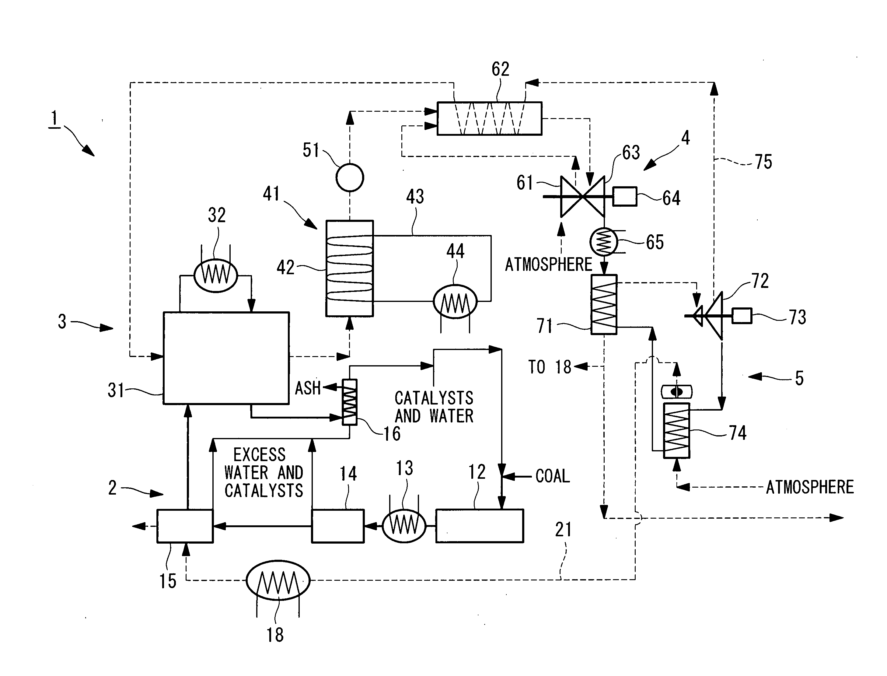
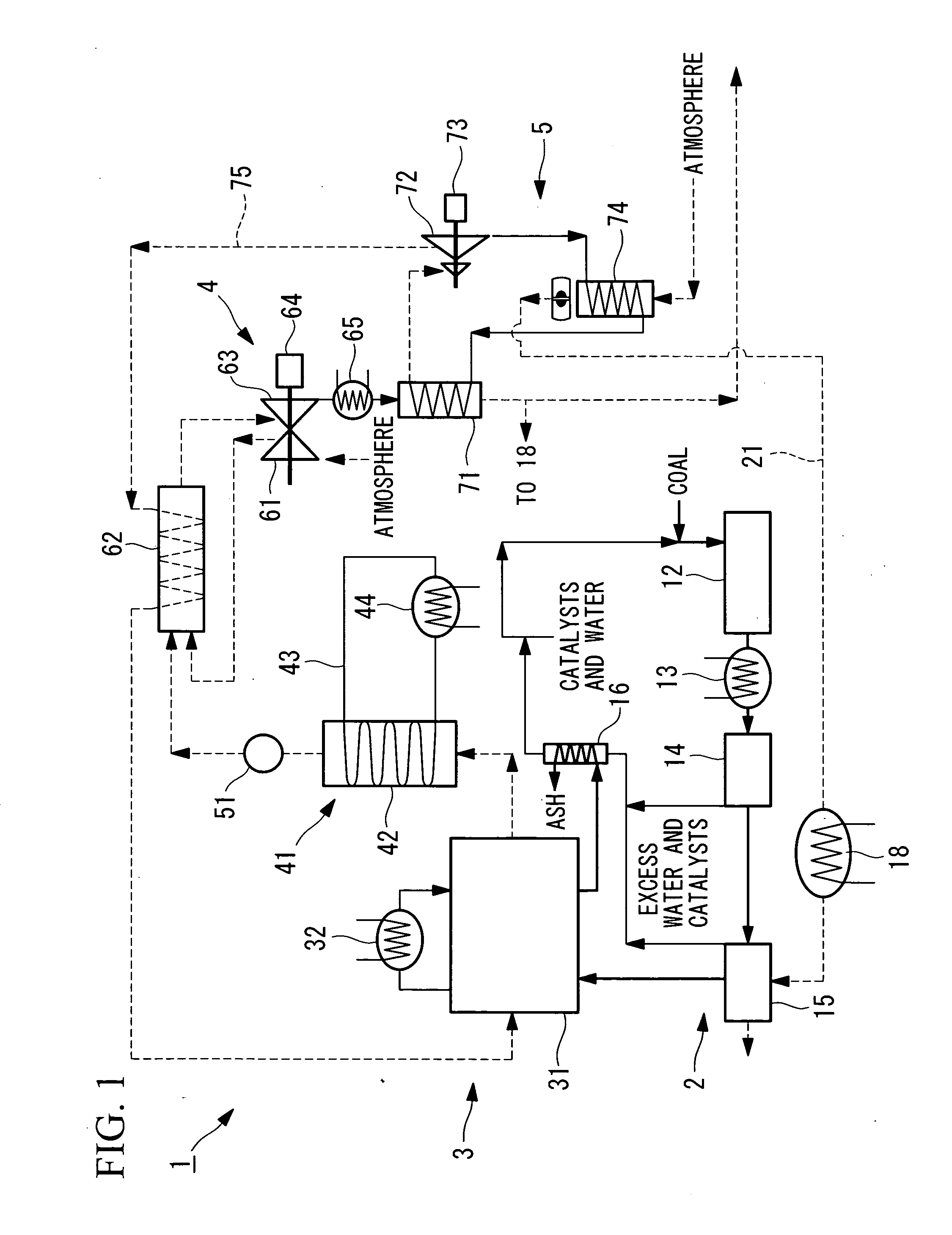
[0038]An integrated coal gasification combined cycle facility according to a first embodiment of the present invention will be described below with reference to FIG. 1.

[0039]FIG. 1 is a schematic diagram for explaining the configuration of the integrated coal gasification combined cycle facility according to this embodiment.

[0040]An integrated coal gasification combined cycle facility 1 according to this embodiment generates power by using, as fuel, low-grade coal with a relatively high moisture content, such as brown coal and sub-bituminous coal.

[0041]As shown in FIG. 1, the integrated coal gasification combined cycle facility 1 includes a pretreatment section 2 that applies pretreatment and drying etc. to coal, a gasification section 3 that performs coal gasification, a gas turbine power generation section (gas power generation section) 4 that generates power by using gas supplied from the gasification section 3, and a steam power generation section 5 that generates power by using...

second embodiment

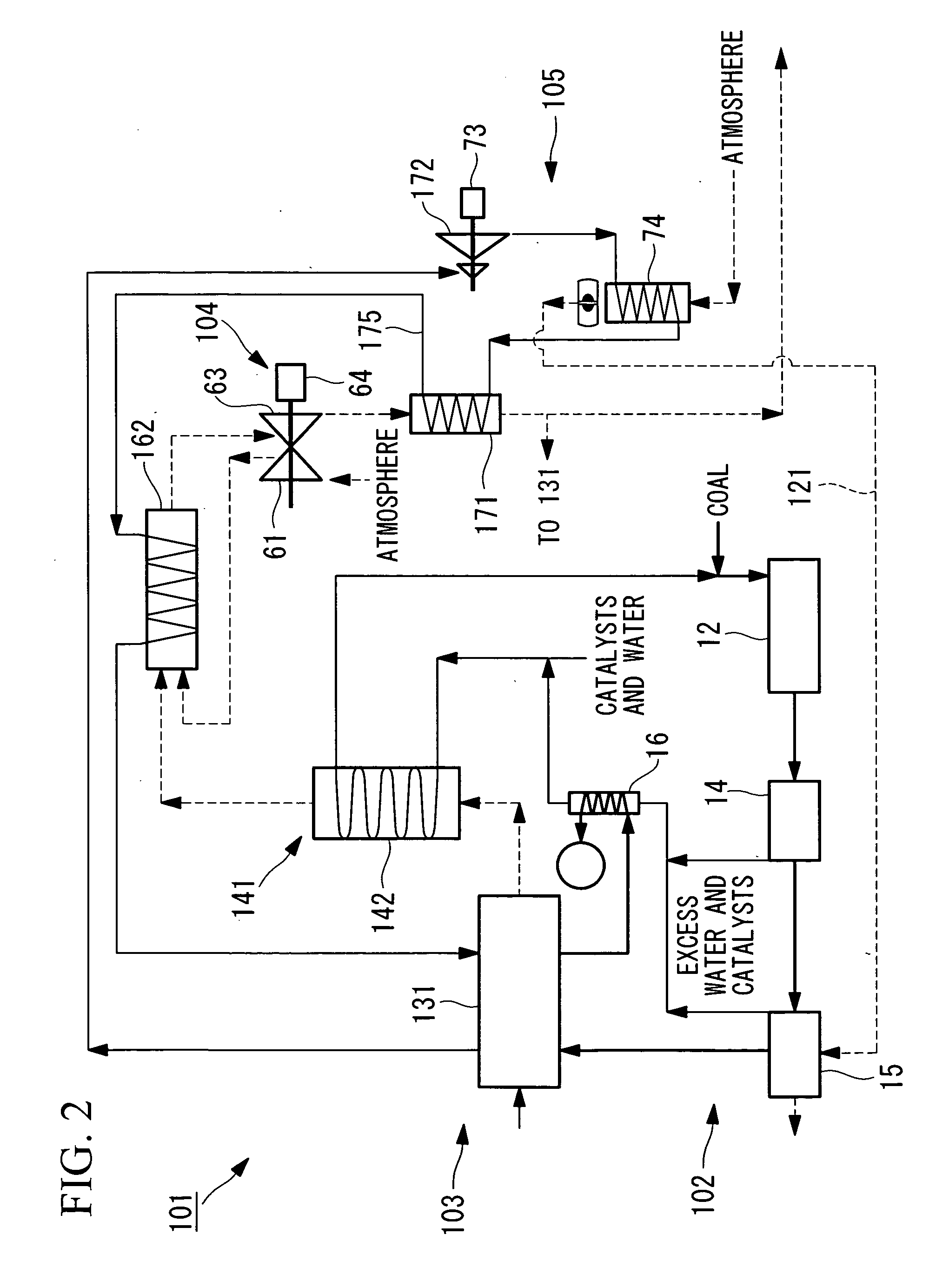
[0157]Next, an integrated coal gasification combined cycle facility according to a second embodiment of the present invention will be described with reference to FIG. 2.

[0158]FIG. 2 is a schematic diagram for explaining the configuration of the integrated coal gasification combined cycle facility according to this embodiment.

[0159]Note that identical reference numerals are assigned to the same components as those of the first embodiment, and a description thereof will be omitted.

[0160]An integrated coal gasification combined cycle facility 101 according to this embodiment differs considerably from the integrated coal gasification combined cycle facility 1 of the first embodiment in that the gasification section 3 is a pressurization system and a different circuit configuration is also used. Therefore, differences from the integrated coal gasification combined cycle facility 1 of the first embodiment will be described below.

[0161]As shown in FIG. 2, the integrated coal gasification c...


PUM


Abstract

An integrated coal gasification combined cycle facility is provided that can prevent a reduction in power generation efficiency even when low-grade coal having a relatively-high moisture content is used. Included are: a gasification section that gasifies supplied coal; a gas power generation section that generates power by using gas supplied from the gasification section; a steam power generation section that generates power by using the heat of exhaust gas discharged from the gas power generation section; and a coal drying unit that dries the coal by using exhaust heat discharged from the steam power generation section and that supplies the dried coal to the gasification section.

Description

TECHNICAL FIELD[0001]The present invention relates to integrated coal gasification combined cycle facilities that are suitable for using, as fuel, low-grade coal such as brown coal and sub-bituminous coal, for example.BACKGROUND ART[0002]An integrated coal gasification combined cycle (hereinafter, referred to as “IGCC”) is a power generation system aiming at higher efficiency and higher environmental performance than a conventional coal-fired power generation, by gasifying coal in combination with C / C (combined-cycle power generation).[0003]Although the IGCC has a great advantage in its ability to use coal, which is an abundant resource, it is known that the advantage is further enhanced by expanding the types of coal to be used.[0004]For example, the IGCC that employs a dry coal feed system can even use coal with a relatively high moisture content, but a high moisture content carried by low-grade coal such as brown coal and sub-bituminous coal causes a reduction in power generation...

Claims


Application Information

Patent Timeline
Patent Type & Authority Applications(United States)
IPC IPC(8): F01K23/10F02C6/18F02C7/22
CPCC10J3/00F01K9/003C10J3/482C10J3/82C10J2300/0903C10J2300/0909C10J2300/093C10J2300/0986C10J2300/1246C10J2300/165C10J2300/1675C10J2300/1892F01K17/06F01K23/067F02C3/28F02C6/18F02C7/224Y02E20/18C10J3/466F22B33/18F23K1/04
Inventor YAMAMOTO, TAKASHIOTA, KATSUHIROISHII, HIROMIKOYAMA, YOSHINORITOKUDA, KIMISHIROMOCHIDA, ISAOHARADA, TATSURO
Owner MITSUBISHI POWER LTD
Why Eureka
Try Eureka