Wind turbine generator and method of controling the same

a technology of wind turbine generator and control method, which is applied in the direction of electric generator control, rotors, vessel construction, etc., can solve the problems of difficult to efficiently generate power, inability to quickly change to normal operation, etc., and achieve the effect of avoiding suppressing the decline of power generation efficiency, and saving a large amount of electricity for swiveling the nacell

Active Publication Date: 2011-09-08
MITSUBISHI HEAVY IND LTD
View PDF6 Cites 4 Cited by
  • Summary
  • Abstract
  • Description
  • Claims
  • Application Information

AI Technical Summary

Benefits of technology

[0010]The present invention has been devised in view of the above situation and it is an object of the present invention to provide a wind turbine generator and a method of controlling the wind turbine generator that can reduce the decline of power generation efficiency even when the wind turbine generator is located where the wind is not always strong.
[0031]Further, according to this method of controlling the wind turbine generator, the swiveling of the nacelle is stopped when the wind speed obtained from the measurement result of the anemometer is not greater than the first threshold. By this, unnecessary frequent swiveling of the nacelle is avoided and also a large amount of electricity for swiveling the nacelle is saved. Therefore, even when the wind turbine generator is located where the wind is not always strong, the decline of the power generation efficiency is avoided.

Problems solved by technology

However, if the nacelle is not directed at the wind direction when the wind gets stronger, it is not possible to promptly change to the normal operation when the wind speed is at the cut-in wind speed or faster.
Especially, for the wind turbine generator located in the areas where it is not always windy, it is difficult to generate power efficiently unless the nacelle is directed to the wind direction.

Method used


Image

  • Wind turbine generator and method of controling the same
  • Wind turbine generator and method of controling the same
  • Wind turbine generator and method of controling the same

Examples


Embodiment Construction

[0036]A preferred embodiment of the present invention will now be described in detail with reference to the accompanying drawings. It is intended, however, that unless particularly specified, dimensions, materials, shape, its relative positions and the like shall be interpreted as illustrative only and not limitative of the scope of the present.

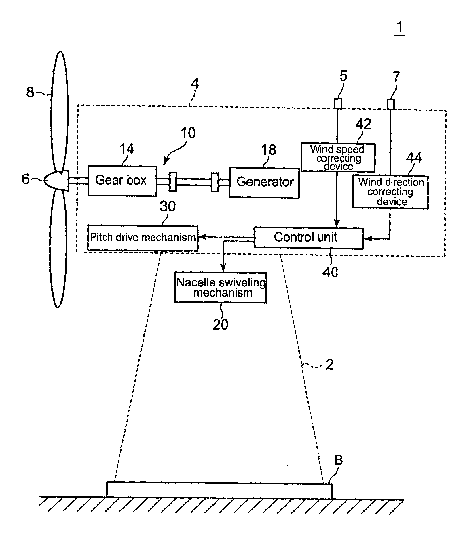
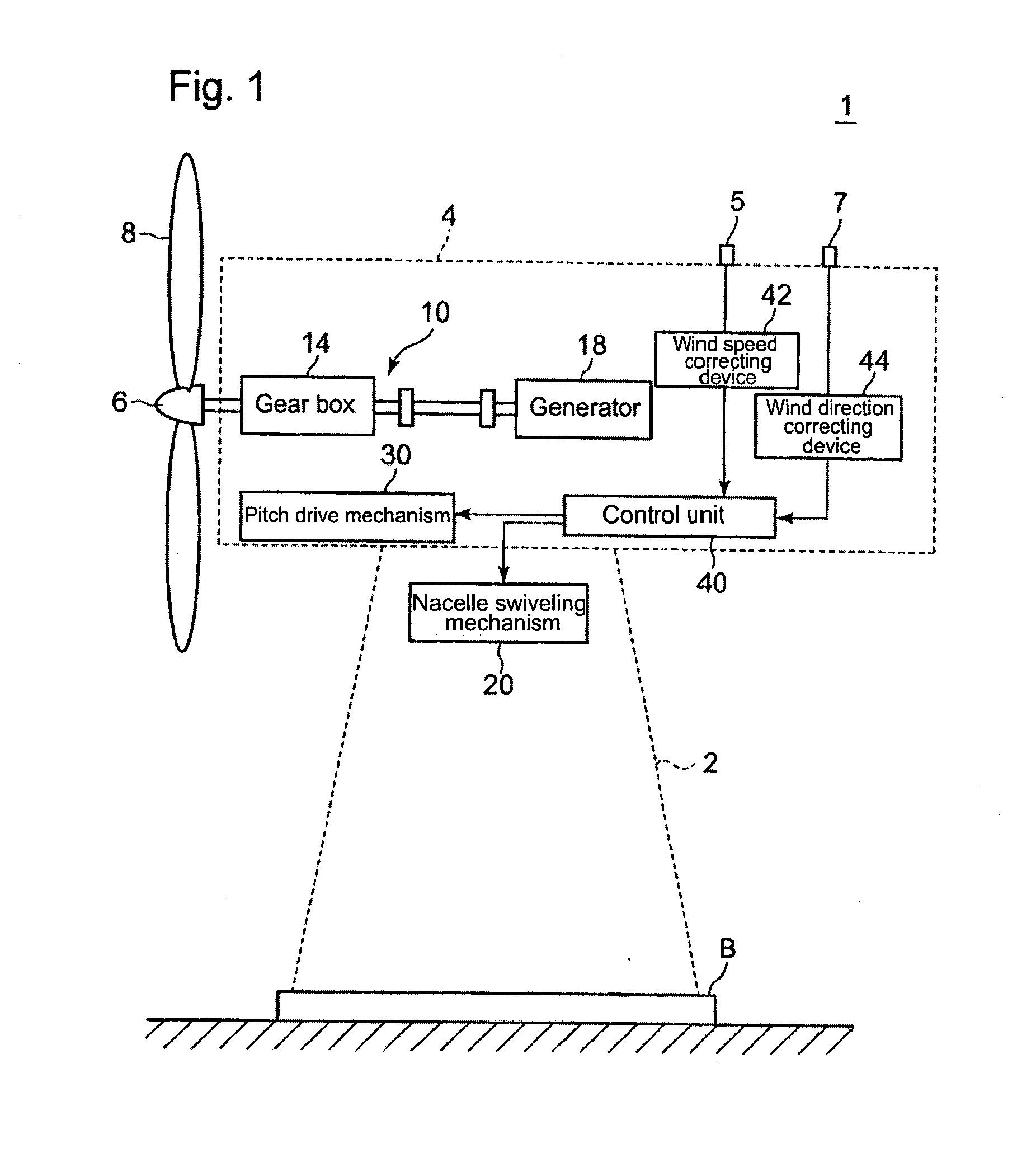
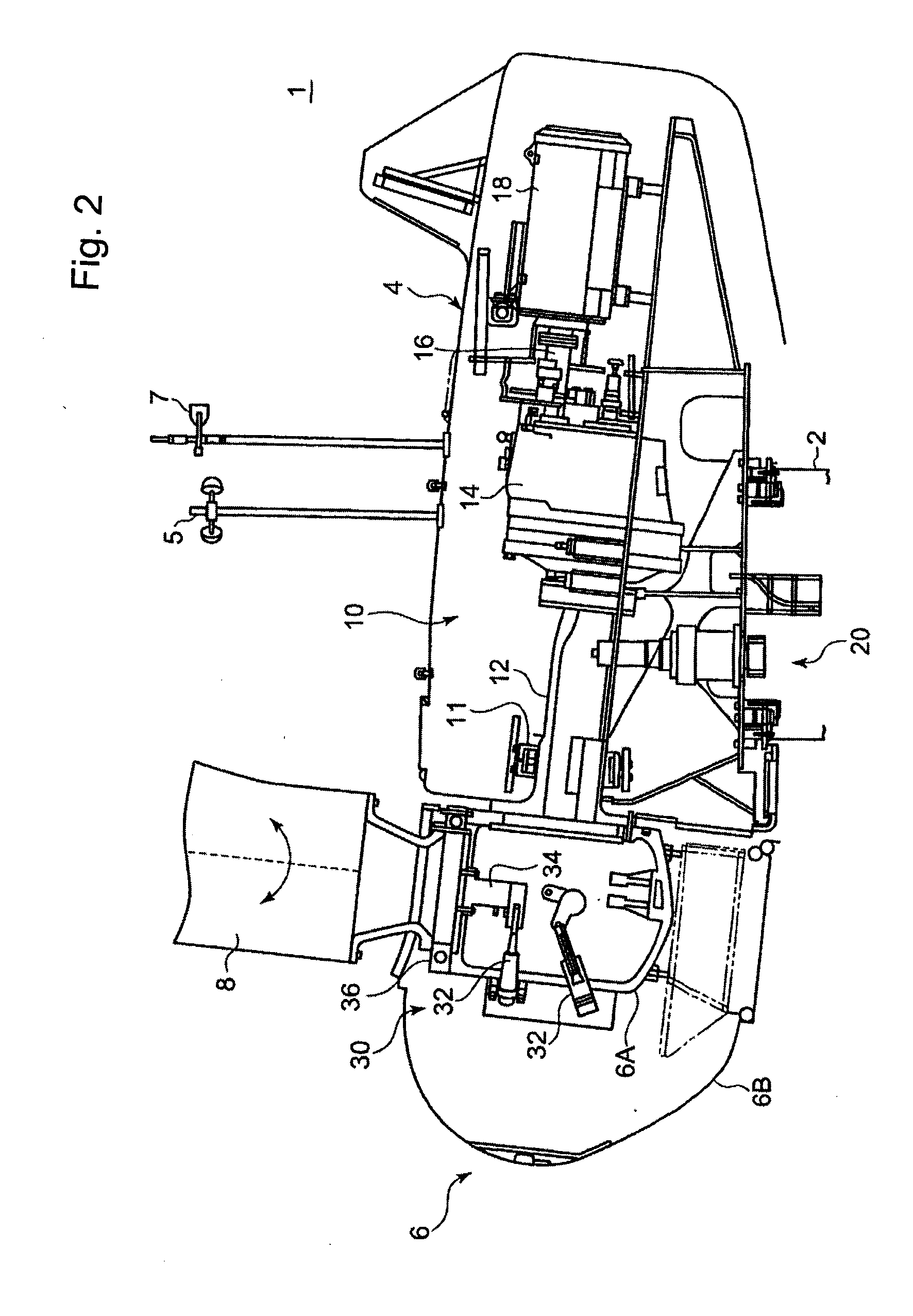
[0037]FIG. 1 is a view showing an example of the overall structure of a wind turbine generator. A wind turbine generator 1 mainly includes, as shown in FIG. 1, a tower 2 provided to stand on a foundation B, a nacelle 4 provided on the upper end of the tower 2, a rotor head 6 provided on the nacelle 4, and a plurality of blades 8 attached to the rotor head 6.

[0038]As shown in FIG. 1, the tower 2 has a column-like shape extending upwardly (to the upper end of FIG. 1) from the foundation B. The tower 2, for example, can be made from a single column-like member or made from a plurality of units aligned in upright direction and coupled to each oth...


PUM


Abstract

The present invention provides a wind turbine generator and a method of controlling the same which can prevent the decline in power generation efficiency even when the generator is located where the wind is not always strong. The wind turbine generator mainly includes an anemometer, an anemoscope, a nacelle swiveling mechanism which turns a nacelle, and a control unit which controls the nacelle swiveling mechanism. The control unit controls the nacelle swiveling mechanism so as to swivel the nacelle based on the wind direction obtained from the measurement result of the anemoscope when the wind speed obtained from the measurement result of the anemometer is greater than a first threshold Vth1 which is smaller than a cut-in wind speed Vcut<sub2>—< / sub2>in, and controls the nacelle swiveling mechanism so as to stop the swiveling of the nacelle when the wind speed obtained from the measurement result of the anemometer is not greater than a first threshold Vth1.

Description

FIELD OF THE INVENTION[0001]The present invention relates to a wind turbine generator and a controlling method for controlling the wind turbine generator, and especially to a wind turbine generator and a method for controlling the wind turbine generator in which a nacelle is swiveled according to measurement results from an anemoscope and an anemometer.DESCRIPTION OF THE RELATED ART[0002]In recent years, from a view point of preserving the global environment, the use of wind turbine generators to generate reusable energy has become popular.[0003]In general, a wind turbine generator comprises a rotor head equipped with blades, a nacelle accommodating a drive train and a rotation axis, and a tower supporting the nacelle. To improve power generation efficiency, most wind turbine generators adopt yaw rotation rotating the nacelle in the wind direction and a pitch control rotating the blades in a pitch direction.[0004]As this type of a wind turbine generator, there is a wind turbine gene...

Claims


Application Information

Patent Timeline
Patent Type & Authority Applications(United States)
IPC IPC(8): F03D7/04F03D9/00
CPCF03D7/0204F05B2270/32F05B2270/321Y02E10/723F03D7/026F05B2270/3201Y02E10/72F03D7/044
Inventor MINAMI, TOHRUTAKEBE, TETSUO
Owner MITSUBISHI HEAVY IND LTD
Why Eureka
Try Eureka