Lifting device

A hoisting device and hoisting rope technology, applied in the direction of hoisting device, spring mechanism, etc., can solve the problems of the hoisting device, such as large size, high manufacturing cost, cumbersome and complicated structure, etc., and achieve light weight, beautiful appearance and structure Simple and compact effect

Inactive Publication Date: 2013-05-08
江苏武东机械有限公司
View PDF8 Cites 3 Cited by
  • Summary
  • Abstract
  • Description
  • Claims
  • Application Information

AI Technical Summary

Problems solved by technology

[0002] The existing lifting device generally adopts a plurality of fixed pulleys distributed in a single row, and the axial direction of each fixed pulley is parallel to the axial direction of the reel. This kind of lifting device has large dimensions, complex structure, and high manufacturing cost. heavy
At the same time, the lifting device generally adopts multiple moving pulleys distributed in a single row. The axial direction of each moving pulley is parallel to the axial direction of the reel, and the radial thickness of the moving pulley is greater than the thickness of the gate, so the shape of the entire lifting device Large size, bulky and complicated structure, and ugly appearance

Method used


Image

  • Lifting device
  • Lifting device

Examples


Embodiment Construction

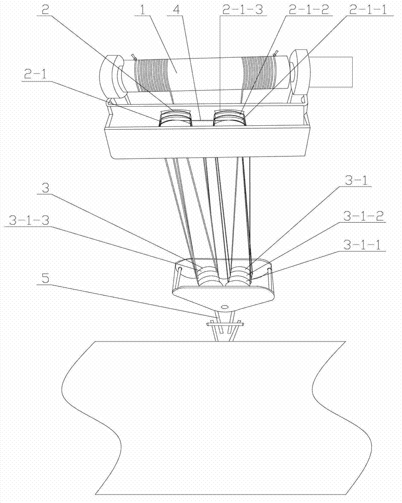
[0018] Such as figure 1 The hoisting device shown is suitable for hoisting on cranes, gantry cranes and hoists, etc. The hoisting device includes a motor-driven reel 1, an upper fixed pulley assembly 2 close to the reel 1 and a lower movable pulley assembly Into 3, the fixed pulley assembly 2 is composed of two fixed pulley blocks 2-1, the axial direction of the fixed pulley block 2-1 is perpendicular to the axial direction of the reel 1, and the movable pulley assembly 3 is composed of two axial directions in eight The font movable pulley block 3-1 is formed, and the hoisting device also has a hoisting rope 4, and the hoisting rope 4 spans the two fixed pulleys on the two fixed pulley blocks 2-1 that play a balancing role. 1 and the fixed pulley block 2-1 are wound sequentially, and finally wound upwards evenly on the reel 1 on the movable pulley block 3-1 and finally fixed on the left and right ends of the reel 1. Adopt the structure of two movable pulley blocks 3-1 of figu...


PUM


Abstract

The invention relates to a lifting device which is suitable for being used for lifting of a traveling crane, a gantry crane, a hoist and the like. The lifting device comprises a winding drum which is driven by a motor, a fixed pulley assembly close to the winding drum on the upper portion of the lifting device and a movable pulley assembly on the lower portion of the lifting device. The fixed pulley assembly is composed of two fixed pulley groups, and the axial directions of the fixed pulley groups are perpendicular to the axial direction of the winding drum. The movable pulley assembly is composed of two movable pulley groups, and the axial directions of the two movable pulley groups are in a V shape. The lifting device is further provided with a lifting rope. After the lifting rope crosses the two fixed pulleys on the two fixed pulley groups, two ends of the lifting rope are respectively downward wound sequentially between the movable pulley groups and the fixed pulley groups, and then, the lifting rope is wound evenly on the winding drum upward on the movable pulley groups and eventually fixedly arranged at the left end and the right end of the winding drum. The lifting device is small in appearance and size, simple in structure and light in weight.

Description

technical field [0001] The invention relates to a hoisting device suitable for driving, gantry cranes, hoists and the like. Background technique [0002] The existing lifting device generally adopts a plurality of fixed pulleys distributed in a single row, and the axial direction of each fixed pulley is parallel to the axial direction of the reel. This kind of lifting device has large dimensions, complex structure, and high manufacturing cost. Heavy. At the same time, the lifting device generally adopts multiple moving pulleys distributed in a single row. The axial direction of each moving pulley is parallel to the axial direction of the reel, and the radial thickness of the moving pulley is greater than the thickness of the gate, so the shape of the entire lifting device The size is large, the structure is heavy and complicated, and the appearance is not beautiful. Contents of the invention [0003] The technical problem to be solved by the present invention is: in orde...

Claims


Application Information

Patent Timeline
Patent Type & Authority Applications(China)
IPC IPC(8): B66D1/00
Inventor 钟晓东钟鲁江
Owner 江苏武东机械有限公司
Why Eureka
Try Eureka